
Installing the Motherboard
User’s Manual
2-15
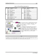
Table 2-2. PN1 and PN2 pin count name list
PIN Name Significance of signal
PIN Name
Significance of signal
PIN 1 +5VDC
PIN 1
Ground
PIN 2 No connection
PIN 2
Reset input
PIN 3 Ground
PIN 3
No connection
PIN 4 No connection
PIN 4
+5VDC
PIN 5 No connection
PIN 5
Ground
PIN6 LED
power
PIN6 Ground
PIN 7 HDD active
PIN 7
Speaker data
PIN 8 Ground
PIN 8
No connection
PIN 9 Power On/Off signal
PIN 9
LED power
PIN 10 Ground
PIN 10 Suspend active
PN1
PIN 11 Suspend signal
PN2
PIN 11 No connection
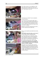
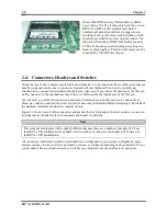
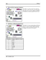
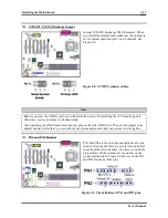
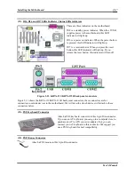
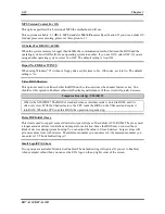
(10). FDC1 Connector
This 34-pin connector is called the “
floppy disk drive
connector
”. You can connect a 360K, 5.25”, 1.2M,
5.25”, 720K, 3.5’’, 1.44M, 3.5” or 2.88M, 3.5”
floppy disk drive.
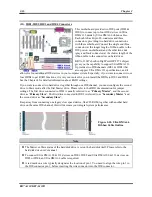
A floppy disk drive ribbon cable has 34 wires and
two connectors to provide the connection of two
floppy disk drives. After connecting the single end to
the FDD1, connect the two connectors on the other
end to the floppy disk drives. In general, people only
install one floppy disk drive on their computer
system.
Note
A red mark on a wire typically designates the location of pin 1. You need to align the wire pin 1 to the
FDC1 connector pin 1, then insert the wire connector into the FDC1 connector.
Summary of Contents for KR7A-133
Page 2: ......
Page 10: ...Chapter 1 KR7A 133 KR7A 133R 1 6 ...
Page 78: ...6 4 Chapter 6 KR7A 133 KR7A 133R ...
Page 84: ...A 6 Appendix A KR7A 133 KR7A 133R ...
Page 90: ...B 6 Appendix B KR7A 133 KR7A 133R ...
Page 104: ...E 4 Appendix E KR7A 133 KR7A 133R ...


