


CR1000/CR1250
13 Appendix
BAL.0351.0 • 2018-08-15
EN - 21
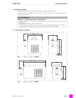
13.3 Connecting diagram flow control
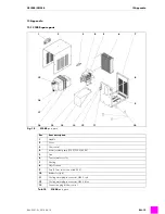
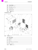
8
Housing
9
On/off switch
10
Fuse (3 fuses for version with 400 V)
11
Rubber foot (x 6)
12
Cooling water plug-in connector, NW 5, red
13
Cooling water plug-in connector, NW 5, blue
14
Connection plug for flow control
15
Motor support
16
Support for coolant container
17
Coolant container bracket (x 2)
18
Coolant container
19
Outlet neck screw cap
20
Filler neck screw cap
Pos.
Item description
Tab. 11
CR1250
spare parts
NOTICE
• This connection option is only suitable for 2-cycle mode.
• The cooling unit disconnects the welding current if the coolant level is low and the torch trigger is pressed.
• The flow control is preset to 0.6 – 0.8 l/min.
Fig. 12
Connecting diagram flow control
Welding power source
Torch trigger
Flow control connector
at front of cooling unit
Flow control
(low cooling liquid volume opens
switch)
Torch control switch
at welding power source
Connection housing


