


ABIROB INSTRUCTION MANUAL
8
To get the best possible service from your ABIROB torch and insure proper servicing, the following peripher-
al equipment will be needed.
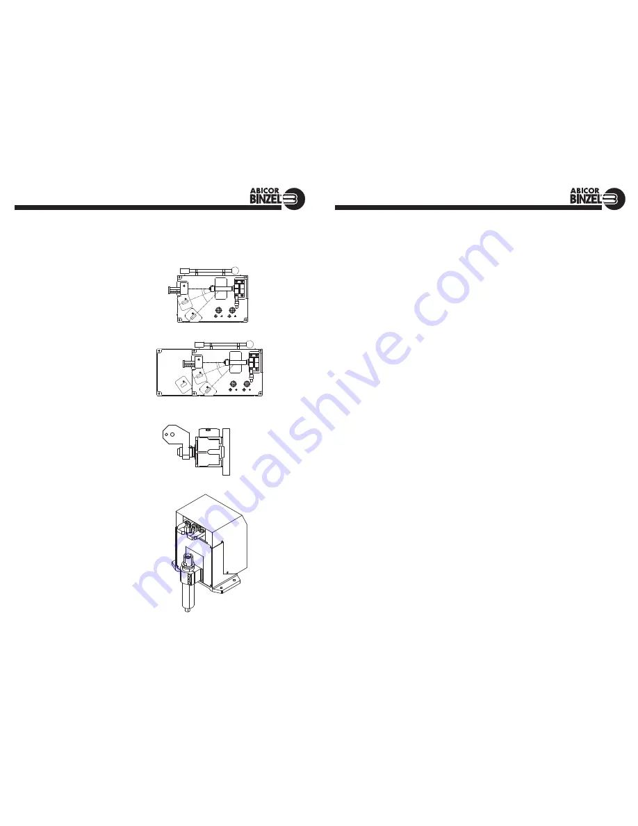
Alignment Jig for ABIROB Necks
Along with the advantages which the design
of the ABIROB brings, the Alignment Jig is
used to check the geometry of the neck outside
the welding booth and make slight adjustments
where necessary.
It is recommended that all new swanneck are
checked and aligned before installation. This
will eliminate any alignment problems which
may have occurred during shipping.
CAT Torch Mount
This provides a secure link between robot and
tool. The CAT robot mount is a 3-dimensional
safety coupling to protect the tool on the robot
or on the handling equipment. Any collision
automatically activates the safety switch built
into the robots emergency stop circuit. The
CAT’s accessory program offers a wide range
of mounts and extensions to reach the neces-
sary TCP.
Cleaning Stations
Spatter from welding process lodges inside the
gas nozzles and this leads to insufficient gas
coverage, and in time, to spatter bridging and
eventually to a short circuit. The result can be a
damaged torch. The cleaning station prevents
this from happening and operates with speed
and precision to reduce manual intervention,
increase the service life of the wear parts
and cut robot downtimes.
ACCESSORIES
837.0500 (A360/A500 standard length necks)
837.0510(A360/A500 long “L” necks)
ABIROB INSTRUCTION MANUAL
9
TROUBLESHOOTING: POROSITY (SUMMARY)
Causes of Porosity
Possible Solutions
BASE METAL CONTAMINATION
Impurities on base metal.
a. Remove contamination; clean surfaces
b. Use of specific wire/gas mix for specific
types of impurities.
FILLER METAL CONTAMINATION
Impurities on filler metal (wire).
a. Replace wire.
b. Install wire-cleaning system.
c. Prevent industrial dust/dirt/grit from
contaminating wire during storage or use.
d. Prevent build-up of aluminum oxide on
exposed aluminum wire surface by using up
quickly.
e. Remove wire from wire drive unit and store
in a sealed plastic bag when not in use for
long periods.
ATMOSPHERIC CONTAMINATION
Drafts, wind, fans, etc.
a. Protect weld from drafts (curtains/screens).
b. Use tapered or bottleneck gas nozzles when
drafts cannot be avoided.
GAS MIXING APPARATUS
1. Too high a gas flow, causing turbulence,
1a. Reduce gas flow.
and/or sucking air at hose connections;
1b. Tighten all hose connection points.
creating venturi effect at end of gas nozzle.
2. Too low a gas flow, causing insufficient gas coverage.
2. Increase gas flow.
3. Damaged or kinked gas lines.
3. Repair or replace
4. Too high an oxygen content.
4. Adjust mixer.
5. Leaks in gas distribution system.
5. Repair leaks.
6. Other impurities in gas – moisture, etc.
6. Overhaul system; fit filters and/or dryers.
7. Inconsistent gas flow (cfh) at the torch connection.
7. Regulate pressure into flow meter for
consistent cfh delivery of gas.
GAS TURBULENCE
1. Excessive spatter build-up in gas nozzle and
1. Clean nozzle and tip regularly; spray with
on contact tip.
anti-spatter fluid.
2. Nozzle damage, causing uneven gas coverage.
2. Replace nozzle.
3. Torch gas ports clogged or deformed.
3. Clean or replace.
4. Super-heated nozzle, causing shielding gas to expand
4. Check duty cycle rating of torch.
rapidly and create return effect at end of nozzle.
Results in contamination of gas by atmosphere.
5. Gas diffuser/nozzle insulator missing.
5. Replace.
6. Too high a gas flow causing venturi effect.
6. Reduce gas flow.
WELDING PARAMETERS, ETC.
1. Too long a wire stick-out; gas nozzle too far
1. Use longer nozzle or adjust stick-out (3/8”
from weld puddle.
minimum or 15 times wire diameter).
2. Bad torch position – too sharp a torch incline
2. Correct torch angle.
causing venturi effect at the end of the nozzle
leading to atmospheric contamination.
3. Excessively wide weld pool for nozzle I.D.
3. Width of the weld pool should be 1.3 times
nozzle I.D.; use suitable wider gas nozzle.
4. Arc voltage too high.
4. Reduce voltage.
5. Too high a travel speed.
5. Reduce speed.
NOTE: Most POROSITY is caused by gas problems, followed by base metal contamination.


