


4
WARNING
Read and follow the manufacturer’s instructions, employer’s safety prac-
tices, and Material Safety Data Sheets (MSDSs).
Only qualified personnel should install, use, or service this material and/or
equipment
WELDING SPARKS can cause fire or explosion
• Do not weld near flammable material
• Do not weld on closed containers.
• Remove combustibles from the work area and/or provide a fire watch.
• Avoid oily or greasy clothing as a spark may ignite them.
ARC RAYS can injure eyes and burn skin
• Always wear correct eye, ear, and body protection
• Always wear a welding helmet with the proper grade filter lens. Protect yourself
and others from spatter arc flash rays by using protective screens, barriers and
welding curtains.
• Always wear protective gloves and clothing to cover exposed skin. This will
aid in the prevention of arc and spatter burns.
ELECTRIC SHOCK can kill.
• Always wear dry installing gloves
• Do not touch live electrical parts.
• Always disconnect power source before hooking up or changing electrodes,
nozzles and other parts.
FUMES AND GASES can be hazardous to your health.
• Keep your head out of the fumes
• Use enough ventilation or exhaust at the arc to keep fumes and gases from
your breathing zone, and general area.
• Fumes from cutting and welding can deplete air quality, causing injury or
death. Always wear an air supplied respirator in confined areas, or if breath-
ing air is not safe.
LOUD NOISE can damage hearing.
• Always wear protective hearing devices to ensure protection when noise levels
exceed OSHA standards.
Alexander Binzel Corporation
650 Medimmune Ct., Suite 110, Frederick, MD 21703-8619
Tel: 301.846.4196 Fax: 301.846.4497 www.abicorusa.com
Read American National Standard Z49.1, “Safety in Welding, and Cutting, and Allied
Processes,” available from American Welding Society, 550 N.W. LeJune Rd., Miami,
FL 33126; OSHA Safety and Health Standards, available from U.S. Government
Printing Office, Washington, DC 20402.
ID 123-4567CI
!
5
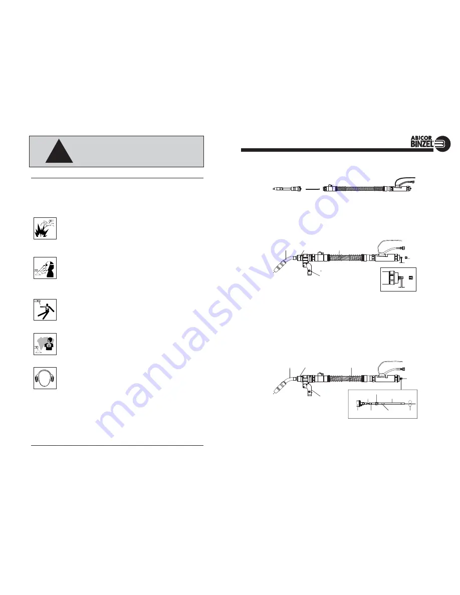
If Installing new Neckliner into Swanneck/Intermediate Module:
1. Unscrew Neck/Module from Cable Assembly.
2. Pull out old Neckliner from Module.
3. Then insert new pre-cut Neckliner into Module.
4. Install Neck/Module back onto Cable Assembly.
Installation of Steel Liners in Euro or Direct Mount Guns
1. Lay the torch out straight and remove the liner retaining nut from the adapter block at the wire feed
end of the cable assembly.
2. Insert and then carefully push the steel liner through the cable assembly until the steel liner stops at
the back of the intermediate module’s liner collet.
3. Measure the excess liner including the liner collet that is sticking out the adapter block of the cable assembly.
4. Pull the liner back out of the assembly and cut to the proper length as follows: cut off from the front
of the liner the length that was measured in the previous step
minus
a 1/4 inch
(approximately 4
rings)
. This will leave an extra 1/8 inch of liner which will put the proper amount of tension on the
liner to allow for good wire feed.
5. Install and lightly tighten the liner retaining nut to complete the installation.
Installation of Plastic Liners in Euro or Direct Mount Guns
1. Lay the torch out straight and remove the liner retaining nut from the adapter plug at the wire feed end of
the cable assembly.
2. Insert and carefully push the plastic liner through the cable assembly until the plastic liner stops at the
back of the intermediate module’s liner collet.
continued on page 6
ABIROB INSTRUCTION MANUAL
NECKLINER AND LINER INSTRUCTIONS
SWANNECK/MODULE
NECKLINER
CABLE ASSEMBLY
CABLE
LINER
NUT
NECK
INTERMEDIATE MODLE
Brass Guide Tube
Area Enlarged
Collet
Adapter
Plug
O-Ring
(Prevent Gas Loss)
Teflon
®
or PA
Liner
Wire Feed
Roll
Liner Retaining Nut
CABLE
LINER
NUT
1/8”
NECK INTERMEDIATE MODLE
MOUNTING BRACKET
Area Enlarged
1/8”
MOUNTING BRACKET


