


Alderon Industries, LLC - Leading Edge Control Products | 218.483.3034 | [email protected] | [email protected] | alderonind.com
Installation Instructions | Page 1
QSG00319_Rev01_Vizzyalarm 1-Zone Indoor Alarm WiFi VZW-02 | November 22, 2021 1:23 PM
Introduction
Before proceeding with the installation or operation of the product, make sure to read all
instructions thoroughly, as well as complying with all Federal, State and Local Codes,
Regulations and Practices. The product must be installed by qualified personnel familiar
with all applicable local electrical and mechanical codes. Refer to the National Electrical
Code (NFPA 70). Failure to properly install and test this product can result in personal injury
or equipment malfunction.
Safety Guidelines
Description of Operation
The Vizzyalarm™ 1-Zone WiFi Alarm is an indoor rated alarm panel, powered by a standard 120VAC wall outlet. The
green power LED will illuminate (solid) when powered. The Vizzyalarm™ is a multipurpose alarm panel that can be used
for a variety of applications, including but limited to: septic tanks, sumps, holding tanks, pump chambers, water tanks, flow,
pressure, condensate, temperature, and any others where a “dry” contact can be connected to the alarm panel. Connect
and register your wireless device to the Alderon™ cloud based Vizzy.site™ to begin monitoring and receiving text and email
alerts for system conditions.
The alarm panel is equipped with audible and visual alarm indication, activated by a normally open or normally closed
sensor wired to the terminals and/or the low battery alarm detection. A variety of sensors can be used such as a float
switch, pressure switch, or any “dry” type sensor that “closes” during an alarm condition (normally open or normally closed).
Installing (3) AA batteries (not included) provides battery backup during power outages. Use the auxiliary contacts to
connect to building automation systems (BAS) and phone dialers. Multiple sensors (signaling device) can be connected for
expanded monitoring.
An alarm condition occurs when the sensor (signaling device) contact is activated, during which the red alarm LED will
illuminate (solid), buzzer will annunciate (solid), and the auxiliary contacts will activate. The alarm condition will stay on until
the sensor is deactivated. If the test/silence pushbutton is pressed during an alarm condition, it will silence the buzzer while
the alarm LED remains on (solid) with activated auxiliary contacts (alarm LED slow flash). The silence condition will reset
when the sensor deactivates and the alarm panel will auto reset for the next alarm cycle.
1. DISCONNECT ALL ELECTRICAL SERVICE BEFORE WORKING ON OR HANDLING THE PRODUCT.
2. DO NOT USE WITH FLAMMABLE OR EXPLOSIVE FLUIDS SUCH AS GASOLINE, FUEL OIL, KEROSENE, ETC.
DO NOT USE IN EXPLOSIVE ATMOSPHERES.
3. ALARM PANEL MUST BE MOUNTED INDOORS. FOR OUTDOOR APPLICATIONS, CONSULT FACTORY.
Specifications
Primary Power
120VAC, 50/60 Hz
Circuit Board Primary Power
11.1VDC, 500mA maximum
Circuit Board Secondary Power
4.5VDC, (3) standard AA batteries
(battery backup; not included)
Field Connection Sensor
3-10VAC/DC, 10mA minimum
(signaling device)
Auxiliary Contacts
30VDC, 700mA maximum
Normally Open; Single Pole, Single Throw
Enclosure
Thermoplastic
5 x 4 x 1.3 (inches)
Type 1, Indoor
Removable cover
Certifications
CSA (US and Canada)
FCC Part 15 (US and Canada)
Three-Year Limited Warranty
LEDs
Green (power), Red (alarm),
and Blue (Vizzy/WiFi)
Buzzer
85 dB @ 10-feet
Wall-Mounted Power Supply
120VAC, 50/60 Hz (input)
11.1VDC, 500mA maximum (output)
(6-foot cord)
Operation, Maintenance, and Installation Manual
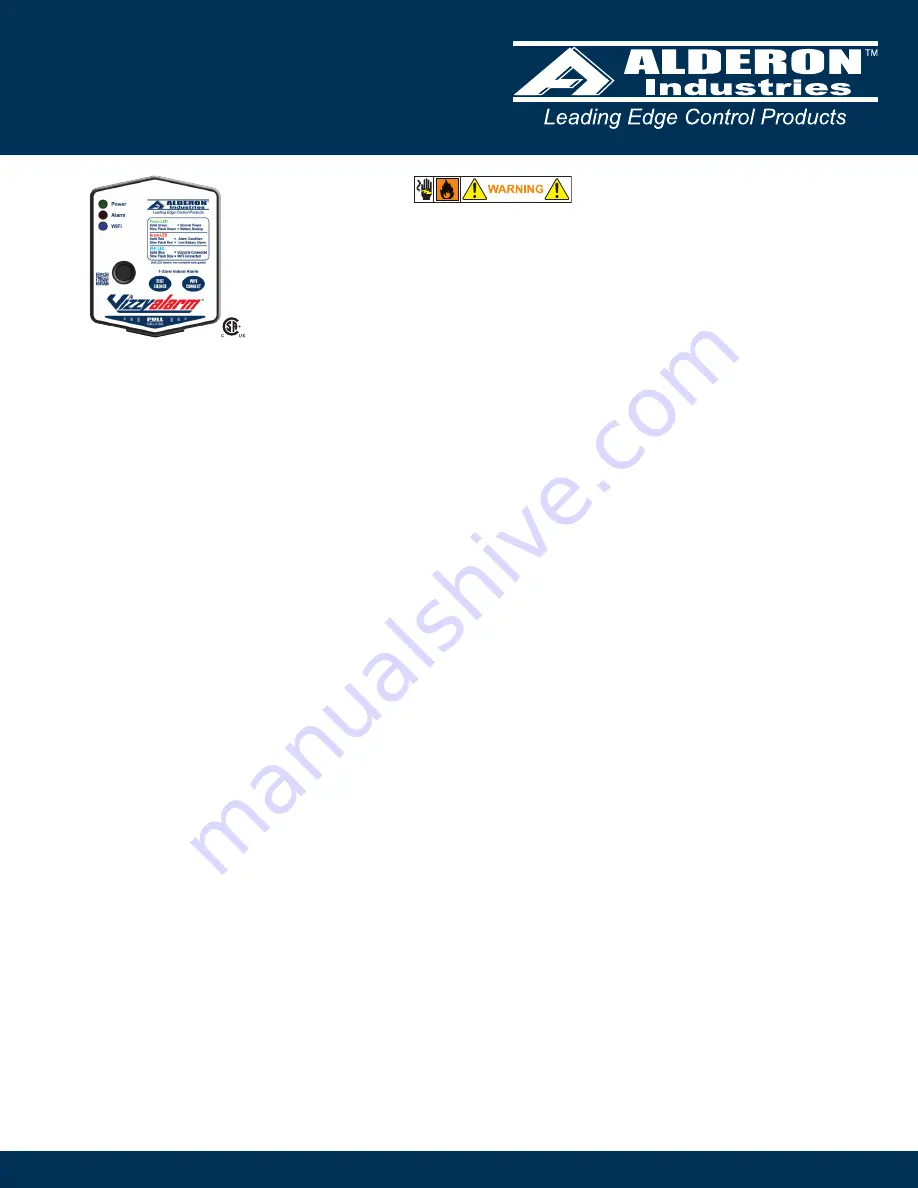
Vizzyalarm
™
1-Zone Alarm
WiFi, Model: VZW-02 | Rated Type 1 (Indoor), Alarm Panel


