background image

When stimulation has stopped due to generator battery depletion

Your patient controller indicates the battery level of your generator. The level ranges from

0% charge to 100% charge. The patient controller also indicates the approximate

stimulation time remaining based on the generator’s current battery level and therapy

settings.
When your implanted generator battery is low, your patient controller displays a low

battery message. When this message appears, you should charge your generator at your

earliest convenience. If you do not charge your generator after the low battery message

appears, your stimulation will eventually stop. When stimulation stops, your controller

will display an alert indicating therapy was turned off due to a low generator battery. You

should charge your generator battery so that therapy can be restored.

NOTE:

▪ To maintain therapy without interruption and improve battery longevity, always

charge your generator before it is depleted completely. If your generator is

repeatedly allowed to deplete completely, its performance or longevity may be

reduced over time.

▪ If your generator is depleted completely, it will take a few minutes for the generator

to turn on again and communicate with your patient controller once you start

charging.

Charging Your Charger

Like your generator, your charger contains a rechargeable battery that needs to be

charged on a regular basis. The battery icon on the charger displays the charger battery

level. The patient controller also displays the charger battery level. If the charger is in

range of the patient controller or connected to it, the battery level is indicated by a

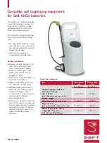
battery icon with colored lights. See the following figure.
Figure 2. Charger battery level

1. Three gray bars: charger is off or

1.

charger battery is depleted

2. One yellow bar: charger will not fully

2.

charge a depleted generator

3. One green bar: charger may not be

3.

able to fully charge a depleted

generator

4. Two green bars: charger can fully

4.

charge a depleted generator

5. Three green bars: charger can fully

5.

charge a depleted generator

NOTE:

▪ One yellow bar indicates you have 30 minutes or less remaining before the charger

turns off due to low battery.

▪ When the charger battery is low, the charger beeps three times every 5 minutes

until the battery is depleted.

7

Summary of Contents for Eterna 16000

Page 1: ...Charging System Eterna Spinal Cord Stimulation System Model 16000 User s Guide...

Page 2: ...California to cause cancer and birth defects or other reproductive harm For more information go to www P65Warnings ca gov Indicates a trademark of the Abbott group of companies Indicates a third party...

Page 3: ...pparel 13 Traveling with Your Charging System 14 Troubleshooting 14 Troubleshooting Charging Issues 15 Service and Ordering Information 17 Appendix A Regulatory Statements 18 Disposal Guidelines for B...

Page 4: ...ii...

Page 5: ...e contraindications warnings precautions adverse effects and the personal identification card related to your neurostimulation system MRI Safety Information Do not bring your charger into the scanner...

Page 6: ...it to dry completely before use Precautions The following precautions apply to this charging system Device components The charging system is for use with the Eterna implantable pulse generator only Y...

Page 7: ...t site while charging your generator stop using the charger Use your patient controller to change the charging mode or contact your physician Heating or discomfort at surgical staples while charging C...

Page 8: ...er your generator and charge the generator without having to manually hold the charger in place The lumbar apparel is worn like a belt around your waist Charging apparel pectoral Charging apparel is u...

Page 9: ...the power icon blinks quickly Battery icon The battery icon illuminates in segments to indicate the charger battery level While the charger is being charged a segment of the battery icon blinks NOTE...

Page 10: ...r to charge your generator To prepare the charger for pairing do the following 1 Ensure that your patient controller and charger are charged 1 2 Place the patient controller near the charger 2 3 Turn...

Page 11: ...e or longevity may be reduced over time If your generator is depleted completely it will take a few minutes for the generator to turn on again and communicate with your patient controller once you sta...

Page 12: ...ter 3 NOTE While the charger is charging it cannot be used to charge the generator If your charger is not charging you may be using an incorrect cable or power adapter Refer to the appendix for techni...

Page 13: ...ly covering the charger 4 5 Wrap the charging apparel around your waist so the charger is over your generator 5 6 Adjust the velcro strap so the apparel is secure around your waist and the charger is...

Page 14: ...the charger over your generator 2 3 Place the counterweight over your shoulder so it rests on your back or around your 3 neck so the counterweight rests on your opposite shoulder NOTE You may need to...

Page 15: ...nsure that the charger is positioned over your generator 5 6 Fasten the buckle 6 NOTE If needed use the excess strap near the buckle to tighten or loosen the apparel Option 2 Loop and charger on same...

Page 16: ...so that you can stop the charger if charging becomes uncomfortable To charge your generator follow these steps 1 Ensure the charger is not connected to an electrical outlet 1 NOTE If the charger is co...

Page 17: ...charging is complete While the charger is charging the generator the charger cannot be turned off If you need to turn off the charger while it is charging the generator move it away from the generato...

Page 18: ...your charging system follow these guidelines Use the travel case to store your charging system Be sure to pack the charging cable and power adapter NOTE For short trips if you plan to travel without...

Page 19: ...he top of your generator Enable sound on the charger to use audible tones while aligning the charger over the generator A series of tones will indicate that charging has begun Avoid sitting on or agai...

Page 20: ...ortable contact your physician The charger is not charging Ensure the charging cable is fully inserted and USB IF certified To determine if a cable is USB IF certified look for markings such as the fo...

Page 21: ...ontroller differently Reconnect the patient controller with the charger Move to a different area or room away from interference in the environment or interference from other devices Avoid operating ot...

Page 22: ...of FCC Compliance This equipment has been tested and found to comply with the limits for a Class B digital device pursuant to part 15 of the FCC rules This device has been tested and found to comply...

Page 23: ...format Table 5 Registration identification information Identifier Type Registration Identifier FCC Registration Number PX2 GMCHG1 Wireless Technology Information The following table summarizes technic...

Page 24: ...th wireless technology symbol is visible on the clinician programmer or patient controller in the upper right corner of the screen When the Bluetooth wireless connection is not active the symbol appea...

Page 25: ...communication from the charger to a legitimate patient controller or clinician programmer Troubleshooting for Wireless Coexistence or Interference Issues If you experience issues with interactions wi...

Page 26: ...tion per the USB protocol Table 9 Implantable pulse generator compatibility for the charging system Description Model Eterna implantable pulse generator 32400 Appendix C Technical Specifications Use t...

Page 27: ...evices contained in IEC 60601 1 2 2014 AMD1 2020 Ed 4 1 and CISPR11 2015 AMD1 2016 AMD2 2019 BS EN 55011 2016 A2 2021 However the device may cause radio interference or may disrupt the operation of ne...

Page 28: ...5 dip in UT for 0 5 cycle 40 UT 60 dip in UT for 5 cycles 70 UT 30 dip in UT for 25 cycles 5 UT 95 dip in UT for 5 s 5 UT 95 dip in UT for 0 5 cycle 40 UT 60 dip in UT for 5 cycles 70 UT 30 dip in UT...

Page 29: ...ance and Manufacturer s Declaration Proximity Fields from RF Wireless Communication Equipment Proximity Test IEC 60601 Test Level Compliance Level Electromagnetic Environment Guidance IEC 61000 4 3 38...

Page 30: ...ic Fields Immunity Test Test Frequency Modulation Immunity Test Level A m IEC 61000 4 39 30 0 kHz Continuous wave 8 134 2 kHz Pulse modulation 2 1 kHz 65 13 56 MHz Pulse modulation 50 kHz 7 5 Appendix...

Page 31: ...p away from rain Ingress protection rating for a device that is protected from the intrusion of solid foreign objects as small as 12 5 mm in diameter and is protected from vertically dripping water wh...

Page 32: ...materials will help to conserve natural resources Authorized representative in the European Community European conformity affixed according to the relevant provisions of European Council Regulation 2...

Page 33: ...Table 16 Symbols and definitions Symbol Definition This device is a recognized component by Underwriters Laboratories UL Inc This device complies with part 18 of the FCC rules 29...

Page 34: ......

Page 35: ......

Page 36: ...abbott com 2023 05 ARTEN600283824 B 600283824...

Reviews: