Turbocharger VTR..4
Seite / Page 13
Demontage und Montage
Kap. / Chap. 5
Disassembly and assembly
ABB Turbo Systems Ltd
10020
- M -
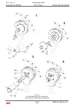
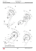
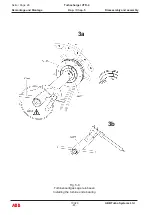
- Remove the hex.-headed screw (76009) (see fig.5-
4/1).
- Release the bearing space cover (46000) with
the puller screws (90900) from the air inlet casing
(76001) and remove it (see fig. 5-4/1).
Caution !
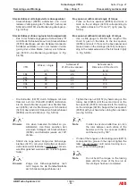
Check the true run B1 of the nipple;
max. tolerance see table below.
Note
If the TE bearing also has to be remo-
ved, further dismantling of the compres-
sor end bearing must be postponed
until the true run values of the nipple
and oil slinger at turbine end have been
checked.
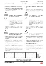
- Remove the socket screws (32181) and locking
washers (32182) and remove the nipple (32185)
(see fig. 5-4/2).
Caution !
Check the true run B2 of the oil slinger;
max. tolerance see table below.
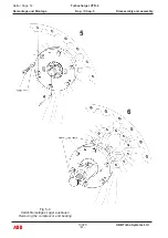
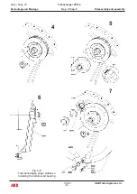
- Fix the holding device (90030) with the hex.-headed
screws (90031) to the oil slinger (32180) (see fig.5-
4/3).
- Unlock the cap nut (32157) and remove it with the
box spanner (90050/90260) (see fig. 5-4/3).
- Remove the locking plate (32114).
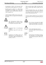
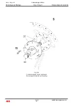
- Screw the extractor (90070) into the holding device
(90030) (see fig. 5-4/4).
- Remove the oil slinger (32180) together with the
extractor (90070) and holding device (90030) (see
fig.5-4/4).
- 6kt-Schrauben (76009) entfernen (s. Fig. 5-4/1).
- Lagerraumdeckel (46000) mit Ab drückschrauben
(90900) vom Luftein trittsgehäuse (76001) lösen
und entfernen (s. Fig. 5-4/1).
Vorsicht !
Rundlauf B1 am Nippel kontrollieren;
max. Toleranz s. Tabelle unten.
Hinweis
Ist das TS-Lager ebenfalls auszubauen,
muss mit der weiteren Demontage des
verdichterseitigen Lagers gewartet wer-
den, bis die Rundlaufwerte des tur-bi-
nenseitigen Nippels und Schmierrades
kontrolliert sind.
- Zyl-Schrauben (32181) und Federringe (32182)
entfernen und Nippel (32185) abziehen (s. Fig.
5-4/2).
Vorsicht !
Rundlauf B2 am Schmierrad kontrollie-
ren; max. Toleranz s. Tabelle unten.
- Festhaltevorrichtung (90030) mit 6kt-Schrauben
(90031) am Schmierrad (32180) befestigen (s.
Fig. 5-4/3).
- Hutmutter (32157) entsichern, und mit Steck-
schlüssel (90050/90260) abschrauben (s. Fig.
5-4/3).
- Sicherungsblech (32114) entfernen.
- Abziehvorrichtung (90070) in Festhaltevorrichtung
(90030) einschrauben (s. Fig. 5-4/4).
- Schmierrad (32180) und Festhaltevorrichtung
(90030) mit Abziehvorrichtung (90070) abziehen
(s.Fig.5-4/4).
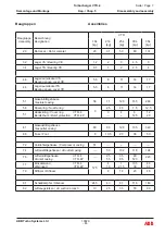
Rundlaufwerte für Nippel und Schmierrad
True run values for nipple and oil slinger
VTR
184
214
254
304
354
B1
0.00 ... 0.04
0.00 ... 0.04
0.00 ... 0.04
0.00 ... 0.05
0.00 ... 0.06 Nippel
Nipple
B2
0.00 ... 0.03
0.00 ... 0.03
0.00 ... 0.03
0.00 ... 0.03
0.00 ... 0.04 Schmierrad
Oil slinger
Summary of Contents for VTR184-21
Page 1: ...Operation Manual VTR184 11 21 ZTL2106 Turbocharging ABB Turbo Systems Ltd...
Page 4: ......
Page 5: ...0 Preliminary remarks Vorbemerkungen...
Page 6: ......
Page 18: ......
Page 19: ...1 Instructions on safety and hazards Sicherheits und Gefahrenhinweise...
Page 20: ......
Page 34: ......
Page 35: ...2 Putting into operation Inbetriebnehmen...
Page 36: ......
Page 53: ...3 Operation and maintenance Betrieb und Unterhalt...
Page 54: ......
Page 99: ...Troubleshooting Beheben von St rungen 4...
Page 100: ......
Page 107: ...Disassembly and assembly Demontage und Montage 5...
Page 108: ......
Page 162: ......
Page 163: ...Taking out of operation Ausserbetriebnehmen 6...
Page 164: ......
Page 180: ......
Page 181: ...Appendix Anhang 7...
Page 182: ......
Page 184: ...10021 ABB Turbo Systems Ltd E Seite Page 2 ABB Turbocharger VTR 4 Anhang Kap Chap 7 Appendix...
Page 228: ......
Page 229: ...Approved lubricating oils Zugelassene Schmier le 8 1...
Page 230: ......
Page 234: ......
Page 236: ......
Page 237: ......
Page 238: ...ABB Turbo Systems AG Bruggerstrasse 71a CH 5400 Baden Switzerland ABB...


