ABB
41
Uniswitc h Operation a nd
Mainte na nc e Manua l
UNI S14GB 05-02
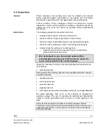
Checkpoints
•
Check that there are no visible signs of, or damage from, partial
discharge.
•
There should also not be any visible signs of connection joints
overheating.
•
All components should perform perfectly and any faulty components
are to be replaced.
Maintenance
instructions
Maintenance serves to preserve trouble-free operation and achieve the
longest possible working life of the switchgear.
It comprises the following closely related activities:
•
Inspection:
Determination of the actual condition
•
Servicing:
Measures to preserve the specified condition
•
Repair:
Measures to restore the specified condition
The inspection and servicing intervals for some of the
equipment/components (e.g. parts subjects to wear) are determined by
fixed criteria, such as switching frequency, length of service and number
of short-circuit breaking operations. On the other hand, for other parts
the length of the intervals may depend, for example, on the different
modes of operation in individual cases, the degree of loading, and also
environmental influences (including pollution and aggressive air).
Time intervals for maintenance work to be carried out always depend on
the operating conditions of the switchgear, and mainly on the mode of
operation, the number of rated and short-circuit current switching
operations, ambient temperature, pollution etc.
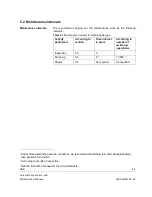
For the Uniswitch switchgear under normal service conditions
maintenance intervals and measures according to Table 5.1 are
recommended. In more demanding conditions (for example areas with
high pollution levels) three year intervals are recommended for all
maintenance measures.
The switch-disconnector’s 1- and 2-spring mechanisms are
maintenance free and do not require any lubrication.
Other relevant
instruction manuals
For circuit-breakers, refer to the
Sace/Calor Emag Maintenance
Instructions for Circuit-breaker
.
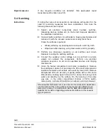
The operation of all protection relays should be checked in accordance
with the manufacturer's instructions.
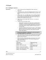
The following operating instructions must also be followed, together with
this instruction manual in the individual cases concerned:
Vacuum circuit-breaker: type VD4
BA 352E
SF
6
circuit-breaker: type HD4
647016
References
If necessary, further details can be taken from the technical
documentation for the switchgear installation (including, for example,
any special operating conditions agreed on).


