ABB
47
Uniswitc h Operation a nd
Mainte na nc e Manua l
UNI S14GB 05-02
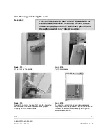
5.5.2.2 Removal of the fuse links.
Figure 5.2
Start from phase L1 (near the door).
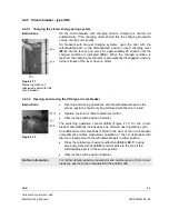
Lift the fuse link (
47
) upwards about 5 mm.
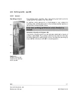
Figure 5.3
Pull out the lower end of the fuse link first and then the upper end.
5.5.2.3 Installing the fuse links
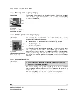
Figure 5.4
The striker pin of the fuse links must be upwards, see the arrow (
47.3
)
(Figure 5.4) on the fuse link. Start the installation from phase L3
(farthest from door)
Push the fuse link first into the upper fuse holder (
47.1
) (Figure 5.4) and
then into the lower holder (
47.2
) (Figure 5.3).
Drag the fuse link downward about 5 mm.

