


50
TZIDC, TZIDC-110, TZIDC-120
DIGITAL POSITIONER | CI/TZIDC/110/120-EN REV. E
… 9 Operation
… Parameterization of the device
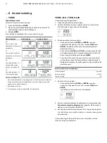
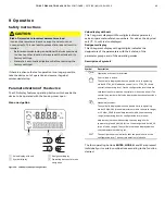
Operating button functions
Control button
Meaning
ENTER
•
Acknowledge
message
• Start
an
action
• Save in the non-volatile memory
MODE
• Choose operating mode (operating level)
• Select parameter group or parameter
(configuration level)
UP
direction
button
DOWN
direction
button
Press and hold all four
buttons for 5 s
Reset
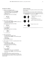
Menu levels
The positioner has two operating levels.
Operating level
On the operating level the positioner operates in one of four
possible operating modes (two for automatic control and
two for manual mode). Parameters cannot be changed or
saved on this level.
Configuration level
On this level most of the parameters of the positioner can be
changed locally. The PC is required to change the limit values
for the movement counter, the travel counter, and the user-
defined characteristic curve.
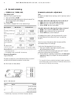
On the configuration level the active operating mode is
deactivated. The I/P module is in neutral position. The
control operation is inactive.
NOTICE
Property damage
During external configuration via a PC, the positioner no
longer responds to the set point current. This may lead to
process failures.
• Before any external parameterization, always move the
actuator to the safety position and activate manual
adjustment.
Note
For detailed information on how to parameterize device, consult
the associated operating instructions and/or configuration and
parameterization instructions.
10
Maintenance
The positioner does not require any maintenance if it is used as
intended under normal operating conditions.
Note
Manipulation by users shall immediately render the warranty for
the device invalid.
To ensure fault-free operation, it is essential that the device is
supplied with instrument air that is free of oil, water, and dust.
11
Recycling and disposal
Note
Products that are marked with the adjacent symbol
may
not
be disposed of as unsorted municipal waste
(domestic waste).
They should be disposed of through separate
collection of electric and electronic devices.
This product and its packaging are manufactured from materials
that can be recycled by specialist recycling companies.
Bear the following points in mind when disposing of them:
• As of 8/15/2018, this product will be under the open
scope of the WEEE Directive 2012/19/EU and relevant
national laws (for example, ElektroG - Electrical
Equipment Act - in Germany).
• The product must be supplied to a specialist recycling
company. Do not use municipal waste collection points.
These may be used for privately used products only in
accordance with WEEE Directive 2012/19/EU.
• If there is no possibility to dispose of the old equipment
properly, our Service can take care of its pick-up and
disposal for a fee.
12
Additional documents
Note
All documentation, declarations of conformity and certificates
are available in ABB's download area.
www.abb.com/positioners
Change from two to one column


