


46
TZIDC, TZIDC-110, TZIDC-120
DIGITAL POSITIONER | CI/TZIDC/110/120-EN REV. E
… 8 Commissioning
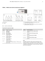
… TZIDC-110 / TZIDC-120
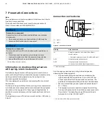
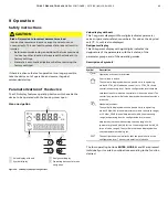
Operating modes
Selection from the operating level:
1. Press and hold down
MODE
.
2. Also press and release
rapidly as often as required. The
selected operating mode is displayed.
3. Release
MODE
.
The position is displayed in % or as a rotation angle.
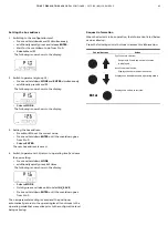
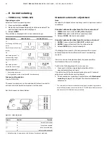
Operating mode
Mode indicator
Position indicator
1.1
Positioning with fixed set
point.
Adjust set point by using
or
.
M10906b
1.2
Manual adjustment* in
the operating range.
Adjust with
or
**
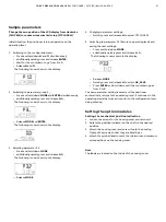
1.3
Manual adjustment*
within the sensor range.
Adjust with
or
**
* Positioning
not
active.
** For high-speed mode, press
and
simultaneously.
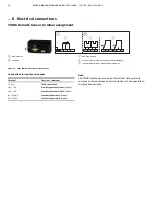
Jumper configuration
Only on TZIDC-120
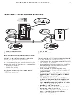
There are two jumpers on the mainboard that can be used to
activate or block simulation mode and write access.
Set the jumpers as shown below:
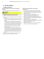
Figure 24: TZIDC-120 jumpers
Jumper Number
Function
1
A
Simulation
blocked*
B
Simulation
enabled
2
A
Write
access
blocked
B
Write
access
activated*
* Default setting (in accordance with Fieldbus Foundation standard)
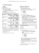
Standard automatic adjustment
Note
Standard Auto Adjust does not always result in optimum control
conditions.
Standard automatic adjustment for linear actuators*
1.
MODE
Press and hold until
ADJ_LIN
is displayed.
2.
MODE
Press and hold until the countdown ends.
3. Release
MODE
; this starts Autoadjust.
Standard automatic adjustment for rotary actuators*
1.
ENTER
Press and hold until
ADJ_ROT
is displayed.
2.
ENTER
Press and hold until the countdown ends.
3. Release
ENTER
; this starts Autoadjust.
If Autoadjust is successful, the parameters will be stored
automatically and the positioner will revert to operating
mode 1.1.
If an error occurs during Autoadjust, the process will be
terminated with an error message.
Perform the following steps if an error occurs:
1.
Press and hold down operating button
or
for
approximately three seconds.
The unit will switch to the operating level, mode 1.3 (manual
adjustment within the measuring range).
2.
Check mechanical mounting in accordance with
Mechanical
mounting
on page 27 and repeat the standard automatic
adjustment.
* The zero position is determined automatically and saved during standard
automatic adjustment, counter-clockwise (CTCLOCKW) for linear actuators
and clockwise (CLOCKW) for rotary actuators.


