


30
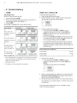
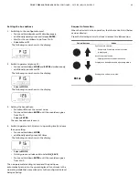
TZIDC, TZIDC-110, TZIDC-120
DIGITAL POSITIONER | CI/TZIDC/110/120-EN REV. E
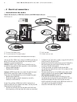
… 5 Installation
… Mechanical mounting
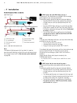
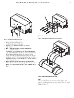
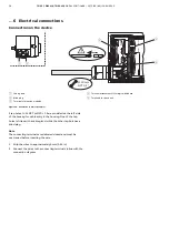
Position of actuator bolt
The actuator bolt for moving the potentiometer lever can be
mounted permanently on the lever itself or on the valve stem.
Depending on the mounting method, when the valve moves the
actuator bolt performs either a circular or a linear movement
with reference to the center of rotation of the potentiometer
lever. Select the chosen bolt position in the HMI menu in order to
ensure optimum linearization. The default setting is actuator
bolt on lever.
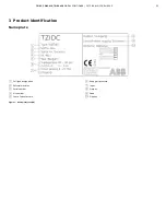
M11031
1
2
3
5
4
1
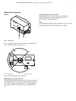
Potentiometer lever
2
Actuator bolts
3
Valve stem
4
Valve yoke
5
Positioner
Figure 11: Actuator bolts on the lever (rear view)
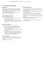
M11032
1
2
3
5
4
1
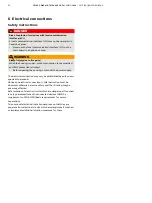
Potentiometer lever
2
Actuator bolts
3
Valve stem
4
Valve yoke
5
Positioner
Figure 12: Actuator bolts on the valve (rear view)
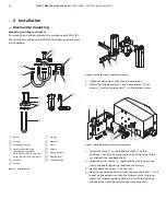
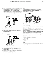
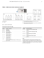
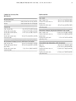
Mounting on rotary actuator
For mounting on part-turn actuators in accordance with
VDI / VDE 3845, the following attachment kit is available:
M10130-01
1
2
3
4
5
6
7
8
9
Figure 13: Components of attachment kit
• Adapter
1
with spring
5
• four M6 screws each
4
, spring washers
3
and washers
2
to fasten the attachment bracket
6
to the positioner
• four M5 screws
7
, Spring washers
8
and washers
9
to
fasten the attachment bracket to the actuator
Required tools:
• Wrench, size 8 / 10
• Allen key, size 3