


8 OI/TTR200-EN Rev. B |
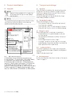
TTR200
3
Use in potentially explosive
atmospheres in accordance with FM
and CSA
NOTICE
— Further information on the approval of devices for use in
potentially explosive atmospheres can be found in the
explosion protection test certificates (at
www.abb.com/temperature).
— Depending on the design, a specific marking in
accordance with FM or CSA applies.
3.1
Ex-marking
FM Intrinsically Safe
Model TTR200-L6
Control Drawing
TTR200-L6H (I.S.)
Class I, Div. 1 + 2, Groups A, B, C, D
Class I, Zone 0, AEx ia IIC T6
FM Non-Incendive
Model TTR200-L6
Control Drawing
TTR200-L6H (N.I.)
Class I, Div. 2, Groups A, B, C, D
CSA Intrinsically Safe
Model TTR200-R6
Control Drawing
TTR200-R6H (I.S.)
Class I, Div. 1 + 2, Groups A, B, C, D
Class I, Zone 0, Ex ia Group IIC T6
CSA Non-Incendive
Model TTR200-R6
Control Drawing
TTR200-R6H (N.I.)
Class I, Div. 2, Groups A, B, C, D
3.2
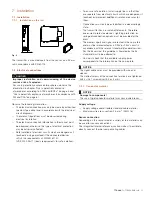
Installation instructions
3.2.1
FM / CSA
The installation, commissioning, maintenance and repair of
devices in areas with explosion hazard must only be carried
out by appropriately trained personnel.
The operator must strictly observe the applicable national
regulations with regard to installation, function tests, repairs,
and maintenance of electrical devices. (e.g. NEC, CEC).
3.2.2
IP protection rating of housing
The temperature transmitter must be installed such that the IP
rating of at least IP 20 is achieved in accordance with
IEC 60529.
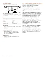
3.2.3
Electrical connections
Grounding
If, for functional reasons, the intrinsically safe circuit needs to
be grounded by means of a connection to the potential
equalization, it may only be grounded at one point.
Intrinsic safety proof
If transmitters are operated in an intrinsically safe circuit, proof
that the interconnection is intrinsically safe must be provided
in accordance with IEC/EN 60079-14 as well as
IEC/EN 60079-25.
The supply isolators / DCS inputs must feature intrinsically
safe input protection circuits in order to eliminate hazards
(spark formation).
In order to provide proof of intrinsic safety, the electrical limit
value must be used as the basis for the EC-type examination
certificates for the equipment (devices); this includes the
capacitance and inductance values of the cables.
Proof of intrinsic safety is said to have been provided if the
following conditions are fulfilled when a comparison is carried
out in relation to the limit values of the equipment:


