


14 OI/TTR200-EN Rev. B |
TTR200
7.3
Power supply
Two-wire technology, polarity safe; power supply lines = signal
lines
NOTICE
Following calculations apply for standard applications. This
should be taken into consideration when working with a
higher maximum current.
Input terminal voltage
— Non-Ex application:
U
S
= 11 ... 42 V DC
— Ex applications:
U
S
= 11 ... 30 V DC
Max. permissible residual ripple for input terminal voltage
— During communication in accordance with HART FSK
"Physical Layer" specification.
Undervoltage detection on the transmitter
— If the terminal voltage on the transmitter falls below a
value of 10 V, this may lead to an output current of I
a
≤
3.6 mA.
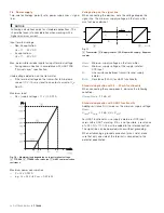
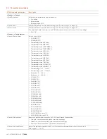
Maximum load
— R
B
= (supply voltage – 11 V) / 0.022 A
Fig. 10: Maximum load depending on input terminal voltage
A
TTR200
B
TTR200 in Ex ia design
C
HART communication
resistance
Maximum power consumption
— P = U
s
x 0.022 A
— e. g. U
s
= 24 V
P
max
= 0.528 W
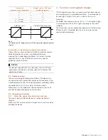
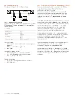
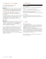
Voltage drop on the signal line
When connecting the devices, note the voltage drop on the
signal line. The minimum supply voltage on the transmitter
must not be undershot.
Fig. 11
A
Transmitter
B
Supply isolator / PCS input with supply / Segment
coupler
U
1min
: Minimum supply voltage on the transmitter
U
2min
: Minimum supply voltage of the supply isolator /
DCS input
R:
Line resistance between transmitter and supply
isolator
R
250
:
Resistance (250 Ω) for HART functionality
Standard application with 4 ... 20 mA functionality
When connecting these components, observe the following
condition:
U
1min
≤ U
2min
- 22 mA x R
Standard application with HART functionality
Adding resistance R
250
increases the minimum supply voltage:
U
2min
:
U
1min
≤ U
2min
- 22 mA x (R + R
250
)
For HART functionality, use supply isolators or DCS input
cards with a HART marking. If this is not possible, a resistance
of ≥ 250 Ω (< 1100 Ω) must be added to the interconnection.
The signal line can be operated with or without grounding.
When establishing a ground connection (minus side), make
sure that only one side of the terminal is connected to the
potential equalization.
A11122
A
B
+
-
U
1
+
U
2
-
R
R
250


