


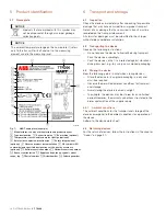


TTR200
| OI/TTR200-EN Rev. B 11
7
Installation
7.1
Installation
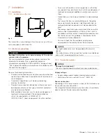
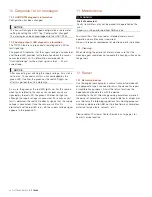
7.1.1
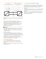
Installation on the rail
Fig. 8
The transmitter is mounted apart from the sensor on a 35 mm
rail in accordance with EN 60175.
7.2
Electrical connections
DANGER
Improper installation and commissioning of the device
carries a risk of explosion.
For use in potentially explosive atmospheres, observe the
information in chapter "Use in potentially explosive
atmospheres according to ATEX and IECEx" on page 5 and
"Use in potentially explosive atmospheres in accordance with
FM and CSA" on page 8!
Observe the following information:
— The electrical connection may only be made by authorized
specialist personnel and in accordance with the electrical
circuit diagrams.
— The relevant regulations must be observed during
electrical installation.
— The electrical connection information in the manual must
be observed; otherwise, the type of electrical protection
may be adversely affected.
— Safe isolation of electrical circuits which are dangerous if
touched is only guaranteed if the connected devices
satisfy the requirements of DIN EN 61140
(VDE 0140 Part 1) (basic requirements for safe isolation).
— To ensure safe isolation, install supply lines so that they
are separate from electrical circuits which are dangerous if
touched, or implement additional isolation measures for
them.
— Connections must only be established in a dead-voltage
state.
— The transmitter has no switch-off elements. Therefore,
overcurrent protective devices, lightning protection, or
voltage disconnection options must be provided at the
plant.
— The power supply and signal are routed in the same line
and must be implemented as a SELV or PELV circuit in
accordance with the relevant standard (standard version).
For the Ex version, the guidelines stipulated by the Ex
standard must to be adhered to.
— You must check that the available supply power
corresponds to the information on the name plate.
NOTICE
The signal cable wires must be provided with wire end
sleeves.
The slotted screws of the connection terminals are tightened
with a size 1 screwdriver (3.5 or 4 mm).
7.2.1
Conductor material
NOTICE
Damage to components!
The use of rigid conductor material may cause wire breaks.
Supply voltage
— Supply voltage cable: flexible standard cable material
— Maximum wire cross-section: 2.5 mm
2
(AWG 16)
Sensor connection
Depending on the sensor model, a variety of line materials can
be used for sensor connections.
The integrated internal reference junction makes it possible to
directly connect thermal compensating cables.
Change from two to one column
A10204
TTR200
+
11
PWR
ERR
1
2
-
1
2
3
4 5
6
108
(4.25)
17,5 (0.69)
114 (4.49)
99
(3.9)
35
(1.38)
OFF ON


