


TTR200
| OI/TTR200-EN Rev. B 19
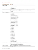
DTM menu path, parameters
Description
<Device> / <Configuration>
<Sensor / Reference junction>
— Internal: use of the internal reference junction of the transmitter when using a thermocouple/compensating cable
(relevant for all thermocouples except for type B)
— External - fixed: transfer of thermal cable/compensating cable via copper material at constant thermostat
temperature
— Without: no cold junction
<Sensor / Reference junction
temperature>
— Relevant for external reference junction, specification of constant external reference junction temperature
Value range: -50 … 100 °C
<Device > / <Parameterize>
<Measuring range of PV / unit>
Selects the physical unit for the sensor measuring signal
Units: °C, °F, °R, K, mV, Ω, mA
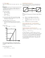
<Measuring range of PV / lower
range value>
Defines the value for 4 mA (adjustable)
<Measuring range of PV / upper
range value>
Defines the value for 20 mA (adjustable)
<Current output / damping>
Configurable τ 63% output signal damping value
Value range: 0 ... 100 s
<Current output / output upon
error > (overrange)
Generates a high alarm signal in the event of a sensor or device error; can be configured 20 ... 23.6 mA.
— Standard 22 mA
<Current output / output upon
error > (underrange)
Generates a low alarm signal when sensor or device errors occur; can be configured from 3.5 … 4 mA
<Device> / <Maintenance>
<Poll address / TAG>
(HART TAG)
Defines the HART TAG name.
— 8 characters, alphanumeric
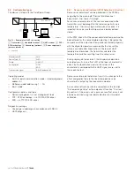
<Poll address / TAG>
(Address (Multidrop))
Specifies the communication type
— Address = 0 conforms to HART operating mode: point-to-point communication, 4 ... 20 mA output signal
— Address = 1 ... 15 conforms to HART multidrop operating mode output signal 3.6 mA, only the digital HART
readings are available
<Adjustment> (Set lower range
value)
Temperature correction for specified / simulated sensor LRV value to desired LRV temperature value
— Set Trim low or lower range value > OK
<Adjustment> (Set upper range
value)
Temperature correction for specified / simulated sensor URV value to desired URV temperature value
— Set Trim high or upper range value > OK
<Adjustment /DAC adjustment
fixed for zero at 4 mA>
Output signal correction for specified / simulated sensor LRV value to 4.000 mA set point
— Analog current measurement value input min. 3.5 ... max. 4.5 mA
<Adjustment /DAC adjustment
fixed for amplification at 20 mA>
Output signal correction for specified / simulated sensor URV value to 20.000 mA set point
— Analog current measurement value input min. 19.5 ... max. 20.5 mA
<Device> <Simulation>
Output signal simulation corresponding to the value specified
— Value range: 3.5 ... 23.6 mA
9.5
Factory settings
The transmitter is configured at the factory. The table below contains the relevant parameter values.
Menu
Designation
Parameter
Factory setting
Device Setup
Write protection
-
No
Input
Sensor Type
Pt100 (IEC60751)
R-Connection Three-wire
circuit
Measured Range Begin
0
Measured Range End
100
Engineering Unit
Degrees C
Damping Off
Process Alarm
Fault signaling
Overrange 22 mA
Change from one to two columns


