4
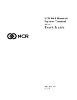
Simplified block diagram of the control module
SPTO 1D2 is shown in Fig. 1.
Fig. 1. Block diagram of the control module SPTO 1D2.
Block diagram
t
Open /
Close
Chann.
4…9
Signal
output
control
Signal
1…3
SPTO 1D2
Enable
SPA-bus
Read
status
Channels
4…13
Channels
1…3
Open/close
output
control
Inter-
locking
Read
status
I
O
SPA-bus
SPA-bus
Indication
E ( )
Channel 7
Q (mA2)
P (mA1)
3I
Measure-
ment
SPA-bus
Indication
Conditional
direct
output
control
&
Indication
1
1