9
Open the media door.
1
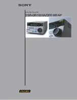
Connect the PC Configurator
Cable Part No. C100/0051
to the Instrument Socket.
2
Connect the PC Configurator
Cable Part No. C100/0051
to the RS232 Serial
Port of the PC.
3
Fig. 4.3 Connecting the PC Configurator Cable
…4
Downloading and Installing the
Operating System Software – Figs. 4.1 to 4.5
8) Connect the instrument to a PC on which the PC
Configurator Software has been installed – see Fig. 4.3