background image

2

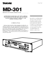
Remove pozidriv screws
(one each side)

Lift up top cover

Remove top cover

Remove PCB locking bar

1

2

3

1

4

Fig. 3.2 Removing the Chassis Top Cover and PCB Locking Bar

Withdraw the instrument
from the case

Remove tamper-proof seal
(if fitted)

Unscrew the jacking screw

1

2

3

Information. Refitting is the

reverse of removal.

Fig. 3.1 Removing the Instrument from its Case

3) Remove the chassis top cover and PCB locking bar –

see Fig. 3.2.

3

Fitting Media Board

Sub-Assembly – Figs. 3.1 to 3.7

Caution. The instrument is vulnerable to

electrostatic damage. Wear an anti-static strap or
dismantle the unit on an anti-static workbench.

1) Isolate the instrument from the power supply.

2) Remove the instrument from its case – see Fig. 3.1.

Summary of Contents for SmartMedia SM2000

Page 1: ...alidating the instrument s warranty 2 Tools Required Medium flat bladed screwdriver No 1 Pozidriv screwdriver Fine tipped soldering iron 1 Introduction This information sheet describes the procedure f...

Page 2: ...ng screw 1 2 3 Information Refitting is the reverse of removal Fig 3 1 Removing the Instrument from its Case 3 Remove the chassis top cover and PCB locking bar see Fig 3 2 3 Fitting Media Board Sub As...

Page 3: ...w the main board from the chassis 3 Disconnect the touchscreen connector from the main board 2 Slot D 1 Connection locking bar Note To disconnect the display flexi circuit it may be necessary to remov...

Page 4: ...out by a Company Approved Service Engineer 3 Fitting Media Board Sub Assembly Figs 3 1 to 3 7 5 Refer to Fig 3 4 and check the part number of the Main Board ve leg below C14 Reverse of Main Board Show...

Page 5: ...is already fitted to the instrument Fig 3 5 Removing the Media Board Sub Assembly Information Refitting is the reverse of removal 1 Check that PCB link LK1 is fitted and ensure it is in the correct po...

Page 6: ...5 Caution When positioning the chassis top cover take care not to damage the EMC contacts Fig 3 7 Refitting the PCB Locking Bar and Chassis Top Cover 3 Fitting Media Board Sub Assembly Figs 3 1 to 3 7...

Page 7: ...e instrument Operating System requires upgrading to 2002 issue 8 0 or later Application Code and 1002 issue 6 0 or later System Code see Fig 1 1 for details of checking the Code versions 1 Isolate the...

Page 8: ...Internal File View button 3 Insert a memory card containing a folder named SM2000 2 4 Downloading and Installing the Operating System Software Figs 4 1 to 4 5 4 Refit the instrument to the case see Fi...

Page 9: ...ect the PC Configurator Cable Part No C100 0051 to the RS232 Serial Port of the PC 3 Fig 4 3 Connecting the PC Configurator Cable 4 Downloading and Installing the Operating System Software Figs 4 1 to...

Page 10: ...rt Recorders Fig 4 5 Creating the Binary Partition 11 Restore the power supply to the instrument and start the download of the new software by clicking on the Program button on the SM2000 Serial Downl...

Page 11: ...fit the instrument to the case see Fig 4 1 18 Restore the power supply to the instrument 19 Follow the on screen instructions and perform touchscreen calibration Caution Do not use sharp objects such...

Page 12: ...ntained herein without notice Printed in UK 02 02 ABB 2002 ABB Ltd Howard Road St Neots Cambridgeshire PE19 8EU UK Tel 44 0 1480 475 321 Fax 44 0 1480 217 948 ABB Inc 125 E County Line Road Warminster...

Reviews: