ABB | SACE Emax 2
Ekip Touch protection trip unit | 7 - Measuring Pro protections
15 | © 2018 ABB | 1SDH001316R0002 - ECN000086018 - Rev. C
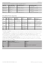
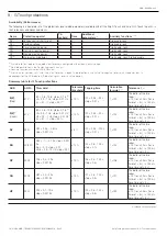
7 - Measuring Pro protections
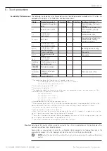
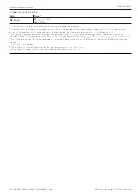
Availability (Performance)
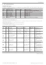
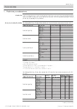
The following is a complete list of the protections (and related parameters) available with all the trip units of the Touch range equipped with an Ekip
Measuring Pro module, in the Protections and Advanced menus:
Name
Protection against
Threshold
Time
Auxiliary functions
(3) (4)
UV
Minimum voltage
X
X
Trip Enable, Lock
OV
Maximum voltage
X
X
Trip Enable, Lock
VU
(1)
Voltage unbalance
X
X
Trip Enable, Lock
UF
(2)
Minimum frequency
X
X
Trip Enable, Lock
OF
(2)
Maximum frequency
X
X
Trip Enable, Lock
RP
Reverse active power
X
X
Trip Enable, Lock
Phase Sequence
Phase sequence error
X
--
Cosφ
Power factor error
X
--
(1)
Protection not active if the highest of the voltages measured is in any case less than 30% of Un.
(2)
Protection not active for voltages <30V.
(3)
Detailed description in the Design Engineer's manual
(4)
Locking Function available via Ekip Connect.
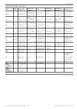
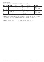
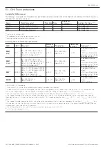
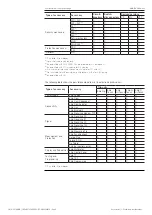
Summary table of Measuring Pro protections
ABB
ANSI
(3)
Threshold
Tolerance
threshold
Time
Calculation
formula t
t
(1)
Tolerance t
t
(2)
UV
27
U8 = 0,05….0,98 Un
step = 0.001 Un
± 2 %
t8 = 0.05…120 s
step = 0.01 s
t
t
= t8
The better of the two values:
± 10 % or ± 40 ms (for a time
set < 5 s) / ± 100 ms (for a
time set
≥
5 s)
OV
59
U9 = 1….1,5 Un
step = 0.001 Un
± 2 %
t9 = 0.05…120 s
step = 0.01 s
t
t
= t9
The better of the two values:
± 10 % or ± 40 ms (for a time
set < 5 s) / ± 100 ms (for a
time set
≥
5 s)
VU
47
U14 = 2…90 %
step = 1 %
± 5 %
t14 = 0.5…60 s
step = 0.5 s
t
t
= t14
The better of the two values:
± 10 % or ± 40 ms (for a time
set < 5 s) / ± 100 ms (for a
time set
≥
5 s)
UF
81L
f12 = 0,9….1 fn
step = 0.001 fn
± 1 %
(4)
t12 = 0,06…300 s
step = 0.01 s
t
t
= t12
The better of the two values:
± 10 % or ± 40 ms (for a time
set < 5 s) / ± 100 ms (for a
time set
≥
5 s)
OF
81H
f13 = 1….1,1 fn
step = 0.001 fn
± 1 %
(4)
t13 = 0,06…300 s
step = 0.01 s
t
t
= t13
The better of the two values:
± 10 % or ± 40 ms (for a time
set < 5 s) / ± 100 ms (for a
time set
≥
5 s)
RP
32R
P11 = -1…-0.05 Sn
step = 0.001 Sn
± 10 %
t11 = 0.5…100 s
step = 0.1 s
t
t
= t11
The better of the two values:
± 10 % or ± 40 ms (for a time
set < 5 s) / ± 100 ms (for a
time set
≥
5 s)
Synchro-
check
25
Ulive = 0.5…1.1 Un; step = 0.001 Un
∆
U = 0.02…0.12 Un; step = 0.001 Un
∆
f = 0.1…1 Hz; step = 0.1 Hz
∆
Cos
φ
= 5…50° elt; step = 5° elt
tsyn = 0.1…3 s; step = 0.1 s
± 10 %
tref = 0.1…30 s
step = 1 ms
-
-
Cyclic
direction of
the phases
47
1-2-3 or 3-2-1
-
-
-
-
Cos
φ
78
Cos
φ
= 0.5…0.95
step = 0.01
-
-
-
-
(1)
Calculation of t
t
is valid for values exceeding the tripping threshold of the protection.
(2)
Valid tolerances with steady-state energized trip unit or trip unit energized by auxiliary power supply, tripping time
≥
100 ms, temperature and
currents within operating limits. If these conditions are not guaranteed, the tripping time tolerance of ± 10 % will become ± 20%.
(3)
ANSI / IEEE C37-2 encoding.
(4)
Valid tolerance for frequencies in the range: fn ± 2 %. For frequency outside the range a tolerance of ± 5 % applies.

