ABB | SACE Emax 2
20 | © 2018 ABB | 1SDH001316R0002 - ECN000086018 - Rev. C
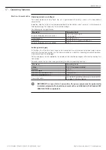
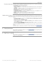
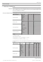
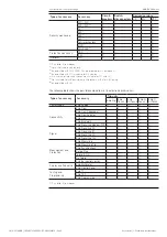
Ekip Touch protection trip unit | 10 - G Hi-Touch protections
10 - G Hi-Touch protections
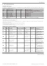
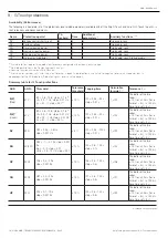
Availability (Performance)
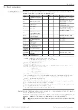
The following is a complete list of the protections (and related parameters) available with all the Ekip G Touch and Ekip G Hi-Touch trip units, in
the Protections and Advanced menus:
Name
Protection against
Threshold Time
Additional
parameters
(2)
Auxiliary functions
(2) (3)
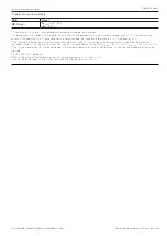
ROCOF
(1)
Rate of change of frequency
X
X
X
Trip Enable, Lock
S2(V)
Voltage control short-circuit
X
X
X
Trip Enable, Lock
RQ2
Reverse reactive power
X
X
X
Trip Enable, Lock
(1)
Not active for voltages <30V.
(2)
Detailed description in the Design Engineer's manual.
(3)
Locking Function available via Ekip Connect.
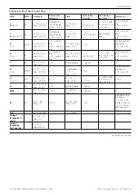
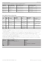
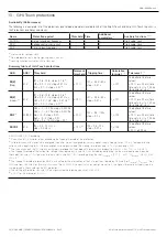
Summary table of G Hi-Touch protections
ABB
ANSI
(1)
Threshold
Tolerance
threshold
Tripping time
Calculation
formula t
t
(2)
Tolerance t
t
(3)
S2(V)
(Step)
51V
I21 = 0.6...10 In; step = 0.1 In
(4)
Ul2 = 0.2…1 Un; step = 0.01 Un
Ks2 = 0.1…1; step = 0.01
(4)
± 10 %
t21 = 0.05…30 s
step = 0.01 s
t
t
= t21
The better of the two
values:
± 10 % or ± 40 ms (for a
time set < 5 s) / ± 100 ms
(for a time set > 5 s)
S2(V)
(Linear)
(5)
51V
I21 = 0.6...10 In; step = 0.1 In
(4)
Ul2 = 0.2…1 Un; step = 0.01 Un
(7)
Uh2 = 0.2…1 Un; step = 0.01 Un
(7)
Ks2 = 0.1…1; step = 0.01
(4)
± 10 %
t21 = 0.05…30 s
step = 0.01 s
t
t
= t21
The better of the two
values:
± 10 % or ± 40 ms (for a
time set < 5 s) / ± 100 ms
(for a time set > 5 s)
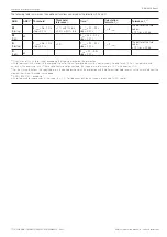
RQ2
(6)
40/32R
Q24 = -1…-0.1 Sn; step = 0.001 Sn
Q25 = -1…-0.1 Sn; step = 0.001 Sn
Kq = -2…2; step = 0.01;
Kq2 = -2…2; step = 0.01
Vmin = 0.5...1.2 Un; step = 0.01
± 10 %
t24 = 0.5…100s
step = 0.1 s
t
t
= t24
The better of the two
values:
± 10 % or ± 40 ms (for a
time set < 5 s) / ± 100 ms
(for a time set > 5 s)
ROCOF
81R
f28 = 0.4…10 Hz / s
step = 0.2 Hz / s
± 10 %
(8)
t28 = 0.5...10 s
step = 0.01 s
t
t
= t28
The better of the two
values:
± 20 % o 200 ms
(1)
ANSI / IEEE C37-2 encoding.
(2)
Calculation of t
t
is valid for values exceeding the tripping threshold of the protection.
(3)
Valid tolerances with steady-state energized trip unit or trip unit energized by auxiliary power supply, tripping time
≥
100 ms, temperature and
currents within operating limits. If these conditions are not guaranteed, the tripping time tolerance of ± 10 % will become ± 20%.
(4)
The trip unit accepts the I21 and Ks2 parameters provided that their product is greater than or equal to 0.6 Hz / s: Ks2 * I21 >= 0.6 Hz / s.
(5)
The tripping threshold of the current for voltage values between Ul2 and Uh2 is calculated by performing the linear interpolation between the
thresholds Uh2 and I21 (first point on the line) and Ul2 and Ks2 * I20 (second point on the line). I
threshold
= [I10 * (1 - ks2) * (U
measured
- Uh2)] / (Uh2 -
Ul2) + I21.
(6)
The tripping threshold of protection RQ2 is calculated by the intersection of the 2 straight lines formed by Q24 and Kq (P
threshold
= Q
measured
* Kq +
Q24) and from Q25 and Kq2 (P
threshold
= Q
measured
* Kq2 + Q25). If the constants Kq and Kq2 are set to 0, the highest threshold will apply (see the
sample graph in the chapter on the RQ protection).
(7)
The setting of thresholds Uh2 and Ul2 must guarantee the following constraint: Uh2 > Ul2.
(8)
± 20 % for the threshold 0.4 Hz / s.

