REM 543 Protection,
Monitoring and Control
Page 37
Technical Reference Manual
Part 1, General
ABB Network Partner
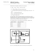
Mathematically the operating condition can be expressed as:
U
c
- (Rh
(ext.)
+ Rh
(int.)
+ R
s
) x I
c
> 20 V ac/dc, where
•
U
c
= operating voltage over the supervised trip circuit
•
I
c
= measuring current through the trip circuit, approximately 1.5 mA (0.99 ... 1.72
mA)
•
Rh
(ext.)
= external shunt resistor value
•
Rh
(int.)
= internal shunt resistor value, 1 k
Ω
•
R
s
= trip coil resistance value
The resistor Rh
(ext.)
must be calculated so that the trip circuit supervision current
through the resistor is low enough not to influence the trip coil of the circuit breaker. On
the other hand, the voltage drop over the resistor Rh(ext.) must not be too high to jeop-
ardize the operating condition presented in the formula above.
The following values are recommended for the resistor Rh
(ext.)
in figure below:
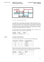
Fig. 4.1.8.-1. Operating principle of the trip circuit supervision (TCS) function.
Operating voltage Uc
Shunt resistor Rh(ext.)
48 V dc
1.2 k
Ω
, 5 W
60 V dc
5.6 k
Ω
, 5 W
110 V dc
22 k
Ω
, 5 W
220 V dc
33 k
Ω
, 5 W
+
Uc
Ic
Rh (ext)
Rs
Rh (int)
1 k
Ω
CMTCS_
A
L A R M
TCS_
BS
TCSSTATE
ALARM
-
20 V
TCSfunc


