installations also in switchyards with double-bus double-breaker and breaker-and-a-
half arrangement. The advantage of such schemes is that the unit protections cover also
for shunt faults in series capacitors and at the same time the voltage inversion does not
appear for faults on the protected line.
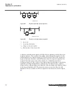
Many installations with line-end series capacitors have available voltage instrument
transformers on both sides. In such case it is recommended to use the VTs for each
particular protection function to best suit its specific characteristics and expectations on
dependability and security. The line side VT can for example be used by the distance
protection and the bus side VT by the directional residual OC ground fault protection.
Apparent impedances and MOV influence
SEMOD168320-285 v2
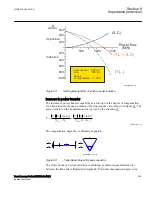
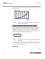
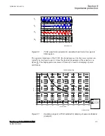
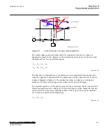
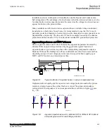
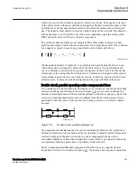
Series capacitors reduce due to their character the apparent impedance measured by
distance IEDs on protected power lines. Figure
presents typical locations of
capacitor banks on power lines together with corresponding compensation degrees.
Distance IED near the feeding bus will see in different cases fault on remote end bus
depending on type of overvoltage protection used on capacitor bank (spark gap or
MOV) and SC location on protected power line.
en06000612_ansi.vsd
~
E
A
0%
33%
50%
66%
K
C
=
80%
33%
33%
50 %
21
100 %
80 %
X
ANSI06000612 V1 EN-US
Figure 99:
Typical locations of capacitor banks on series compensated line
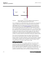
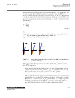
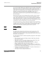
Implementation of spark gaps for capacitor overvoltage protection makes the picture
relatively simple, because they either flash over or not. The apparent impedance
corresponds to the impedance of non-compensated line, as shown in figure
K
C
= 0%.
en06000613.vsd
jX
R
KC = 0%
KC = 80%
LOC = 0%
KC = 50%
LOC = 50%
jX
jX
R
R
KC = 2 x 33%
LOC = 33%, 66%
KC = 80%
LOC = 100%
jX
jX
R
R
IEC06000613 V1 EN-US
Figure 100:
Apparent impedances seen by distance IED for different SC locations
and spark gaps used for overvoltage protection
1MRK 504 163-UUS A
Section 8
Impedance protection
Transformer protection RET670 2.2 ANSI
223
Application manual
Summary of Contents for RELION RET670
Page 1: ...RELION 670 SERIES Transformer protection RET670 Version 2 2 ANSI Application manual ...
Page 2: ......
Page 48: ...42 ...
Page 64: ...58 ...
Page 74: ...68 ...
Page 104: ...98 ...
Page 194: ...188 ...
Page 518: ...512 ...
Page 618: ...612 ...
Page 648: ...642 ...
Page 666: ...660 ...
Page 672: ...666 ...
Page 682: ...676 ...
Page 844: ...838 ...
Page 868: ...862 ...
Page 956: ...950 ...
Page 964: ...958 ...
Page 1004: ...998 ...
Page 1014: ...1008 ...
Page 1015: ...1009 ...

