Weidmüller maxGUARD, Manual
Get your hands on the Weidmüller maxGUARD user manual for free download. This essential manual provides detailed information on using and configuring this product effectively. Make sure to download it from manualshive.com to maximize your understanding and utilization of the maxGUARD features.
Share
Download


Reviews:
No comments
Related manuals for maxGUARD

XF-1000ES
Brand: XINDAK Pages: 2

Liebert MPX Elementary
Brand: Emerson Pages: 16

Di-Strip
Brand: Emerson Pages: 20
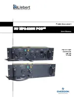
3U MP2-220N POD
Brand: Emerson Pages: 18

Liebert MicroPOD MP2-210K
Brand: Emerson Pages: 16

MPHR2204
Brand: Emerson Pages: 51

Liebert PPC 15-30 kVA
Brand: Emerson Pages: 24

Network Poewr MPH2
Brand: Emerson Pages: 36

Avocent PM 3000
Brand: Emerson Pages: 66

POWER360 P360-DOCK
Brand: Panamax Pages: 8

EPD-2083
Brand: Ekars Pages: 8

CW 1251P
Brand: Elgar Pages: 24

PDUMV15NET
Brand: Tripp Lite Pages: 2

PDUMV30HVNET
Brand: Tripp Lite Pages: 4

RLC-1040
Brand: Rotel Pages: 12

IT-REFERENCE 7i
Brand: Furman Pages: 28


