Datwyler IPDU-A Series, User Manual
The Datwyler IPDU-A Series is a cutting-edge power distribution unit designed to enhance the efficiency and reliability of your data center. With its advanced features and user-friendly interface, this product ensures seamless power management. Feel free to download the comprehensive User Manual for free at our website for detailed instructions.
Share
Download


Reviews:
No comments
Related manuals for IPDU-A Series

PX
Brand: Raritan Pages: 5

Dominion Px
Brand: Raritan Pages: 3

ETA-20SH
Brand: ETA Systems Pages: 16

Dominion Px
Brand: Raritan Pages: 7

SLIM
Brand: Siemens Pages: 4

XJ-L Busway System
Brand: Siemens Pages: 6

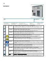
SIVACON 8PS LR Series
Brand: Siemens Pages: 8

SIVACON 8PS BD2C EESC Series
Brand: Siemens Pages: 6

SIVACON 8PS LD Series
Brand: Siemens Pages: 8
SIVACON S 8PQ Series
Brand: Siemens Pages: 40

WL Series
Brand: Siemens Pages: 362

IL78A
Brand: DayTronic Pages: 16

TI4400 GPU-24
Brand: Tesla Pages: 43

PDUMH15NET2LX
Brand: Tripp Lite Pages: 24

PDUMH15HVNET
Brand: Tripp Lite Pages: 36

PDUMH15AT
Brand: Tripp Lite Pages: 48

138-118
Brand: Raytheon Anschütz Pages: 98

0 734 54
Brand: LEGRAND Pages: 2


