


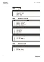
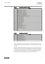

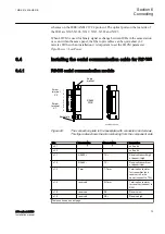

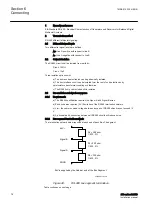


Pin
Name 2-wire
Name 4-wire
Description
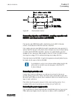
2–wire:
Connect pin X1:1 to
pin X1:6 and pin X1:2
to pin X1:5.
Termination (2-wire):
Connect pin X1:1 to
pin X1:3
Termination (4-wire):
Connect pin X1:1 to
pin X1:3 and pin X1:4
to pin X1:6
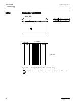
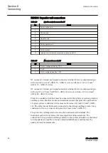
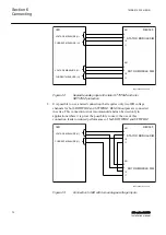
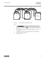
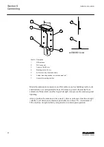
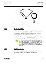
The distance between connection points should be < 1200 m (3000 ft), see Figures
. Only the outer shielding is connected to the IED with the cable clamp,
. The cable shield shall be properly connected to the IED
chassis with the cable clamp, where the maximum open conductor length is 40 mm
(1.57”) between clamp and terminals, see Figure
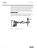
. If double shielded cable is
used, the inner cable shielding should be connected at the external equipment end
only. At the IED terminal end, the inner shield should be isolated. The inner and
outer shieldings are connected to the external equipment according to the
installation instructions for the actual equipment. Use insulating tape for the inner
shield to prevent contact with the IED chassis. Make sure that the IEDs are
properly earthed with as short connections as possible from the earth screw, for
example to an earthed frame.
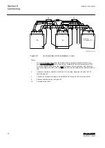
The IED and the external equipment should preferably be connected to the same
battery.
Section 6
1MRK 514 026-UEN B
Connecting
74
670 series 2.2 IEC
Installation manual
Summary of Contents for Relion 670 series
Page 1: ...RELION 670 SERIES 670 series Version 2 2 IEC Installation manual ...
Page 2: ......
Page 10: ...4 ...
Page 18: ...12 ...
Page 24: ...18 ...
Page 88: ...82 ...
Page 100: ...94 ...
Page 110: ...104 ...
Page 111: ...105 ...


