


Section 6
Connecting
6.1
Making the electrical connection
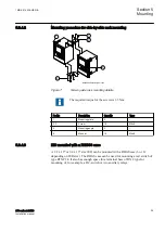
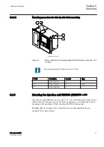
6.1.1
IED connectors
SEMOD127536-1 v1
6.1.1.1
Overview
SEMOD129364-5 v1
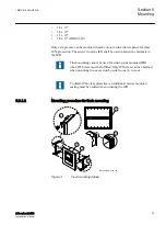
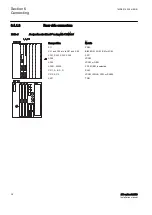
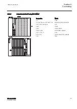
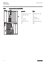
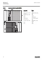
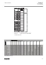
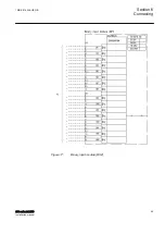
The quantity and designation of connectors depend upon the type and size of the
IED. The rear cover plates are prepared with space for the maximum of HW
options for each case size and the cut-outs that are not in use are covered with a
plate from factory.
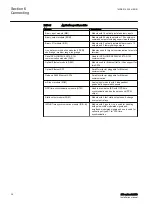
Overview
M11562-3 v9
Table 2:
Basic modules
Module
Description
Power supply module (PSM)
Including a regulated DC/DC converter that
supplies auxiliary voltage to all static circuits.
•
An internal fail alarm output is available.
Numerical module (NUM)
Module for overall application control. All
information is processed or passed through this
module, such as configuration, settings and
communication. The module provides four SFPs
for Ethernet traffic.
Local Human machine interface (LHMI)
The module consists of LEDs, an LCD, a push
button keyboard and an ethernet connector used
to connect a PC to the IED.
Transformer input module (TRM)
Transformer module that galvanically separates
the internal circuits from the VT and CT circuits. It
has 12 analog inputs.
Analog digital conversion module (ADM)
The module converts the VT and CT analog
signals from the TRM to digital signals processed
by the NUM. Carrier for communication boards.
Combined backplane module (CBM)
The module has two main purposes: to distribute
supply voltages from the PSM to the other
modules and to act as a communication carrier
via its two buses, CompactPCI for fast I/O and
communication and CAN for slow I/O.
Universal backplane module (UBM)
The module is used to interconnect the TRM and
the ADM. It also connects the NUM with the LHMI
1MRK 514 026-UEN B
Section 6
Connecting
670 series 2.2 IEC
35
Installation manual
Summary of Contents for Relion 670 series
Page 1: ...RELION 670 SERIES 670 series Version 2 2 IEC Installation manual ...
Page 2: ......
Page 10: ...4 ...
Page 18: ...12 ...
Page 24: ...18 ...
Page 88: ...82 ...
Page 100: ...94 ...
Page 110: ...104 ...
Page 111: ...105 ...


