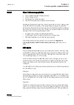
The difference between a readable/writable object and a write-only
object is not visible in the Communication Management tool of
PCM600. An object is of write-only type if it is located on an IEC
61850 Oper.ctlVal data attribute. In this case, the GI enabling and
other possible event configuration settings are meaningless.
3.3.2.3
Class 1 event overflow
The size of the Class 1 event buffer in the IED is 500 events. The IEC 60870-5-103
standard does not define any method of indicating Class 1 event buffer overflows.
Instead, the standard suggests that the master performs a general interrogation
integrity scan every 15 minutes (or more), to detect indications that have not been
updated spontaneously.
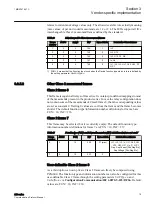
The IED contains a special overflow Class 1 ASDU 1 indication. The default setting
of this overflow indication is FUN = 10, INF = 255. The FUN/INF definition can be
changed if required. This object creates an ON event when the overflow occurs. It is
also possible to take the overflow operation completely out of use and operate without
any overflow indication as the IEC 60870-5-103 standard defines. The IEC
60870-5-103 instances can also be configured differently.
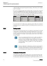
There are four setting parameters related to the IEC 60870-5-103 Class 1 overflow
operation in the IED. The setting parameters are located in
Configuration/
Communication/IEC 60870-5-103/I3C0n
(parameter suffix n = 1 or 2, depending
on the instance).
•
Class1OvInd n
: takes the overflow object into use. Settings: No indication, Both
edges, Rising edge.
•
Class1OvFType n
: defines the Function Type (FUN) for the overflow indication.
•
Class1OvInfNo n
: defines the Information Number (INF) for the overflow
indication.
•
Class1OvBackOff n
: defines how many events have to be emptied from the Class
1 event buffer until new ones are collected. Default setting is “500” (meaning the
whole event buffer must be emptied).
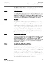
The overflow operation preserves the oldest events in the buffer. The overflow Class
1 event is given the time stamp of the indication that first created the overflow
situation. In other words, the indication event is lost and replaced with the Class 1
overflow event.
3.3.2.4
Chronology of Class 1 events
In some special cases it is possible that Class 1 events can be transmitted in a wrong
chronological order. However, this never occurs for the same object and the time
stamps for all Class 1 events are always correct. Reason for the disorder can be the
filtering time of a physical digital input, or suppressing of the intermediate state of
four-pole objects. Event detection time and reporting time are different in these cases.
Section 3
1MRS757647 C
Vendor-specific implementation
14
620 series
Communication Protocol Manual
Summary of Contents for Relion 620 Series
Page 1: ...RELION PROTECTION AND CONTROL 620 series IEC 60870 5 103 Communication Protocol Manual...
Page 2: ......
Page 40: ...34...
Page 43: ...37...


