background image

Self-powered feeder protection 

1MDB07217-YN 

REJ603 


Product version: 3.0 

Issued: 2017-11-21 


Revision: E  


17 

ABB 

15.


Dimensions and mounting 

The REJ603 have been supplied with mounting 
clamps facilitating the easy flush mounting on 
the panel.  

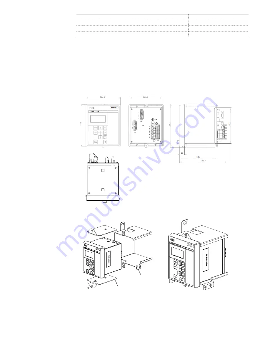
The panel cut-out for flush mounting: 

With appropriate mounting accessories the 
REJ603 can also be mounted on the secondary 
circuit breakers and Ring Main Units.  


Height :   


137.0 ± 1.0 mm  


Width :    


121.5 ± 1.0 mm 


Thickness of panel :  

1.5 – 4.0 mm 


Figure 3. Dimension of REJ603 – Flush mounting 


Figure 4. Typical mounting of relay in RMU (Mounting plate and bracket not supplied along with relay) 

Mounting bracket 

Mounting plate 

Summary of Contents for REJ603

Page 1: ...Relion 605 series Relion 605 series Self powered feeder protection REJ603 Product Guide Relion 605 series ...

Page 2: ...s 13 15 Dimensions and mounting 17 16 Selection and ordering data 18 17 Terminal diagram 20 18 References 19 19 Document revision history 19 Disclaimer The information in this document is subject to change without notice and should not be construed as a commitment by ABB ABB assumes no responsibility for any errors that may appear in this document Copyright 2017 ABB All rights reserved Trademarks ...

Page 3: ...n one unit with the best performance usability in its class and are based on ABB s in depth knowledge of protection and numerical technology REJ603 offers pre configured functionality which facilitates easy and fast commissioning of switchgear To emphasize the simplicity of relay s usage only application specific parameters needs to set within the relay s intended area of application The relay als...

Page 4: ...o prevent unwanted tripping s due to energizing of transformers The low set stages for overcurrent and earth fault protection are equipped with selectable characteristics Definite time DT and Inverse definite minimum time IDMT The relay features standard IDMT characteristics according IEC 60255 151 Normal Inverse NI Very Inverse VI Extremely Inverse EI Long time Inverse LI and IDMT characteristics...

Page 5: ...y shows three phase current and the earth current in secondary terms The values measured can be accessed using on the local HMI The relay continuously measures thermal level 6 Event log To collect sequence of events SoE information the relay incorporates a non volatile memory with a capacity of storing 250 events with associated time stamps with resolution of 1 ms Event log includes protection ope...

Page 6: ... the protection pick up 11 Inputs and outputs The relay is equipped with four 1A or 5A analog current inputs 3 for phase current and 1 for earth current measurements The relay has optional one binary input The binary input is configured for remote external trip and protection blocking The relay has a one capacitor discharge impulse output 24V DC 100 mJ for tripping circuit breaker with sensitive t...

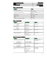
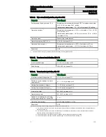
Page 7: ...alue Uaux nominal 24 240 V AC 50 and 60 Hz 24 240 V DC Uaux variation 85 110 of Uaux 20 4 264 V AC 80 120 of Uaux 19 2 288 V DC Burden of auxiliary voltage supply under quiescent Pq operating condition 2 0 W 4 5 W Ripple in the DC auxiliary voltage Max 15 of the DC value at frequency of 100 Hz Table 7 Energizing inputs Description Value Rated frequency 50 60 Hz Current inputs Rated current In 1 A ...

Page 8: ...sensing time 25 ms Table 9 Impulse voltage trip output Description Value Rated voltage 24 V Pulse duration 50 msec Energy 100 mJ Table 10 Bi stable power output relay Description Value Rated voltage 60 V AC DC 0 3 A Continuous contact carry 2 A 24V DC Make and carry for 3 0 s 4 A 24V DC Make and carry for 0 5 s 6 A 24V DC Breaking capacity when the control circuit time constant L R 40 ms at 24 110...

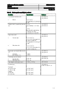
Page 9: ...85 C IEC 60068 2 2 Dry cold test Working Storing 96 h at 25 C 96 h at 40 C IEC 60068 2 1 Damp heat test cyclic 2 cycles 12 h 12 h at 25 C 55 C Rh 93 IEC 60068 2 30 Change of temperature test Cyclic 3 hours at 25 C 3 hours at 55 C Number of cycles 5 IEC 60068 2 14 Table 14 Electromagnetic compatibility tests Description Type test value Reference 1 MHz 100 kHz burst disturbance test Common mode Diff...

Page 10: ...mmunity test Common mode Differential mode 4 0 kV 1 2 50 µs 2 0 kV 1 2 50 µs bi stable O P and power supply port Not applicable for low energy trip output 2 0 kV 1 2 50 µs 1 0 kV 1 2 50 µs bi stable O P and power supply port IEC 60255 26 IEC 61000 4 5 Power frequency magnetic field immunity test Continuous Short duration 3 s 100 A m 300 A m IEC 60255 26 IEC 61000 4 8 Power frequency immunity test ...

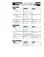
Page 11: ... test Isolation resistance 100 M Ω at 500 V DC IEC 60255 27 Protective bonding test Resistance 0 1 Ώ 20 A 60 s IEC 60255 27 Table 17 Mechanical tests Description Type test value Reference Vibration tests Response Endurance Withstand 10 150 Hz 0 075 mm 1 0g 1 sweep axis 10 150 Hz 2 0 g 20 sweeps axis IEC 60255 21 1 class I Shock tests Response Endurance Withstand 5 g 3 pulses in each direction 15 g...

Page 12: ...2 ABB Table 19 Product safety Description Type test value LV directive 2014 35 EU Standard EN 60255 27 2014 EN 60255 1 2010 Table 20 EMC compliance Description Type test value EMC directive 2014 30 EU Standard EN 60255 26 2013 Table 21 RoHS compliance Description Complies with RoHS directive 2011 65 EU ...

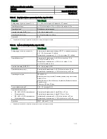
Page 13: ...k 0 02 1 6 in steps of 0 01 Operation time accuracy 2 IEC ANSI RI HR and FR characteristics class E 5 or 30 ms class E 7 5 or 30 ms of theoretical value for I set value 0 2 Reset ratio IDMT 0 96 and DT 0 98 1 The relay s minimum powering current is 0 07 x In when currents in three phase and 0 18 x In when current in a single phase 2 Operation time accuracy for protection functions when relay is in...

Page 14: ... Operation accuracy 1 External earth measurement 3 0 x In for value 1 2 In 3 0 x I for value 1 2 In Internal earth measurement 9 0 x In for value 1 2 In 9 0 x I for value 1 2 In Operate time delay DMT t0 0 04 64 s in steps of 0 01 Operation time accuracy 1 External earth measurement 2 0 of set value or 30 ms Internal earth measurement 10 0 of set value or 30 ms Operating curve type IEC 60255 151 N...

Page 15: ... steps of 0 01 Ratio Setting 10 50 in steps of 1 Table 28 Thermal overload protection 3Ith 49 Parameter Value Range Initial thermal level of apparatus 0 0 0 100 in steps of 1 Reference current leading to thermal calculation Ib 0 1 1 5 x In in steps of 0 1 Heating time constant of object 𝜏 1 0 300 min in steps of 1 0 Cooling time constant of object 𝜏 𝑠 1 0 300 min in steps of 1 0 Alarm value alm 50...

Page 16: ...itch on to fault 80 ms Figure 2 Switch on to fault characteristics of relay REJ603 Note 1 Operation time accuracy for protection functions shall be as indicated in Table 22 27 when relay is in energised condition The operation time measured when relay is in un energised condition shall be as per switch on to fault characteristics Table 29 and Figure 2 Please refer application manual for operation ...

Page 17: ...ing on the panel The panel cut out for flush mounting With appropriate mounting accessories the REJ603 can also be mounted on the secondary circuit breakers and Ring Main Units Height 137 0 1 0 mm Width 121 5 1 0 mm Thickness of panel 1 5 4 0 mm Figure 3 Dimension of REJ603 Flush mounting Figure 4 Typical mounting of relay in RMU Mounting plate and bracket not supplied along with relay Mounting br...

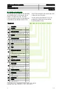
Page 18: ...N B 3 4 N N J Description 1 3 Relay type Feeder overcurrent protection REJ 4 6 Relay series identity Self powered or dual powered relay 603 7 Standard IEC B 8 Analog input output Phase and Earth current input 1A 1 Phase and Earth current input 5A 2 9 Spare None N 10 Spare None N 11 Binary input output slot 1 None N 1 Binary Input including power supply 24 240V AC DC 1VA 1 1 12 Communication None N...

Page 19: ...ered feeder protection 1MDB07217 YN REJ603 Product version 3 0 Issued 2017 11 21 Revision E 19 ABB Your ordering code Digit 1 3 4 6 7 8 9 10 11 12 13 14 15 16 17 18 Code Figure 5 Ordering key for complete relay ...

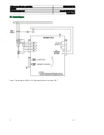
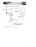
Page 20: ...powered feeder protection 1MDB07217 YN REJ603 Product version 3 0 Issued 2017 011 21 Revision E 20 ABB 17 Terminal diagram Figure 6 Terminal diagram of REJ603 V3 0 with external earth connection through CBCT ...

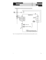
Page 21: ...lf powered feeder protection 1MDB07217 YN REJ603 Product version 3 0 Issued 2017 11 21 Revision E 21 ABB Figure 7 Terminal diagram of REJ603 V3 0 with external earth connection through residual connection ...

Page 22: ...Self powered feeder protection 1MDB07217 YN REJ603 Product version 3 0 Issued 2017 011 21 Revision E 22 ABB Figure 8 Terminal diagram of REJ603 V3 0 with internal earth connection ...

Page 23: ...tains the latest product documentation such as application manual technical presentation and so on The selection tool on the Web page helps you find the documents by the document category and language The Features and Application tabs contain product related information in a compact format 19 Document revision history Document revision Date Product version History A 2015 06 06 3 0 Self powered fee...

Page 24: ...dia Ltd Distribution Automation Maneja Works Vadodara 390013 India Phone 91 265 6724402 Fax 91 265 6724407 www abb com mediumvoltage www abb com substationautomation 1MDU07217 YN E Copyright 2017 ABB All rights reserved ...

Reviews: