39
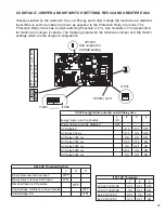
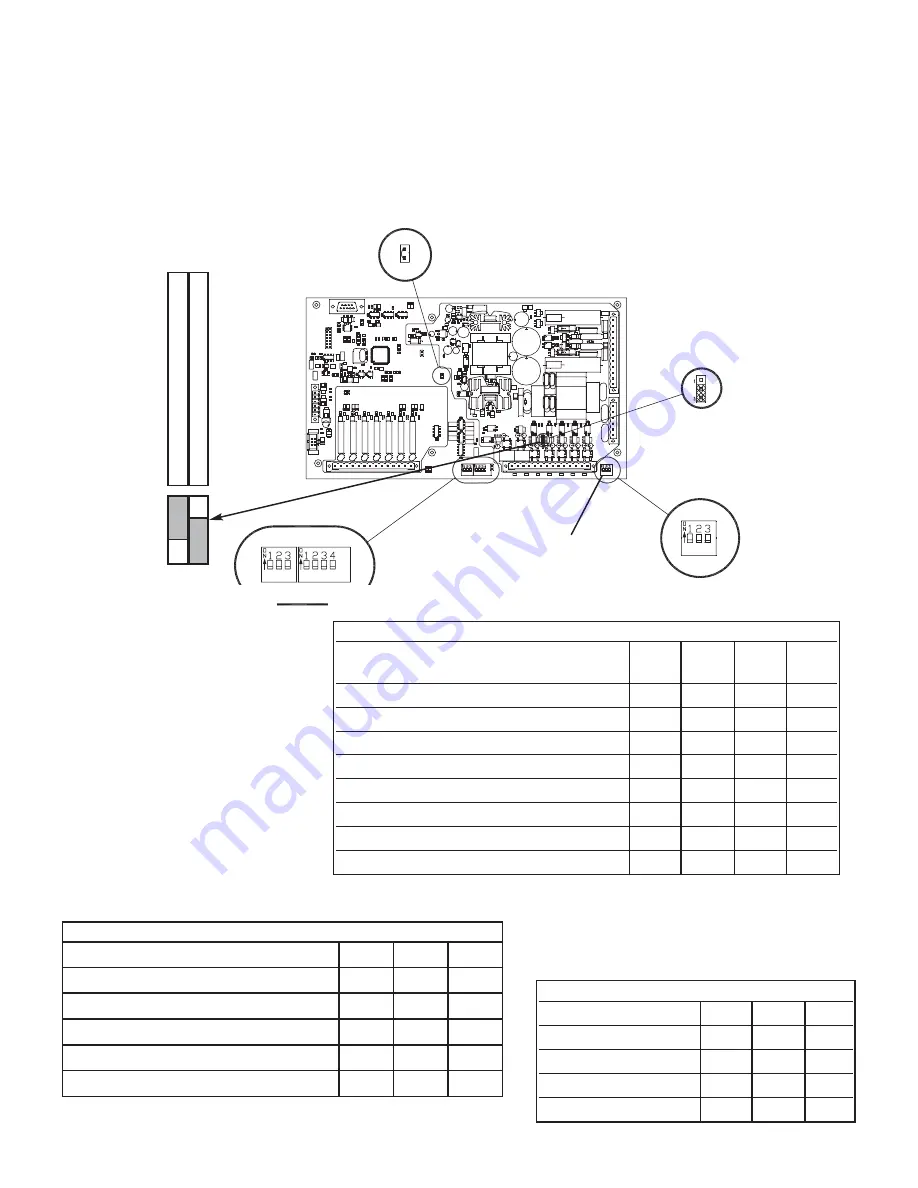
8.0 DEFAULT JUMPER AND DIP SWITCH SETTINGS REV 02 AND GREATER ED2.0
Unless specified by the customer, the Low Energy and Under Voltage trip functions are disabled.
Input three is set for Auxiliary trip mode as opposed to the Protection Relay trip mode. The
Protection Relay mode has a lower switching threshold (12 V). See Illustration 13 in Appendix A
for Switch and Jumper locations. The following represents the functional Jumper and Dip Switch
settings which are the shipped configuration.
I1004 Energy failure auto trip and UV delay time
1
2
3
4
Energy failure Auto Trip Enabled
ON
Energy failure Auto Trip Disabled
OFF
UV Disabled
OFF
OFF
OFF
UV Delay 500 ms
OFF
ON
OFF
UV Delay 1000 ms
ON
ON
OFF
UV Delay 2000 ms
OFF
OFF
ON
UV Delay 3000 ms
ON
OFF
ON
UV Delay 4000 ms
OFF
ON
ON
UV Delay 5000 ms
ON
ON
ON
I1002
I1004
I1001 UV Threshold
1
2
3
220-240 VAC/VDC
OFF
OFF
OFF
100-127 VAC/VDC
ON
OFF
OFF
48-60 VAC/VDC
OFF
ON
OFF
24-30 VAC/VDC
OFF
OFF
ON
1
2
3
P
R
O
T
E
C
T
I
O
N
N
O
R
M
A
L
1
2
3
I1001
JP1019
Add Jumper for
33 Watt setting
I1002 UV Threshold Setting
1
2
3
Binary input used as Aux Open
OFF
Binary input 3 used as Safe Open
ON
Not Used leave in Off position
OFF
Undervoltage: CB Block in Open Position
OFF
Undervoltage: CB
ON
On filter card
Summary of Contents for R-MAG
Page 12: ...Figure 3 Interrupter Assembly 15 5 kV 1250 A 12 ...
Page 13: ...Figure 4 Interrupter Assembly 15 5 kV 2000 A 13 ...
Page 14: ...Figure 5 Interrupter Assembly 15 5 kV 3000 A 3700 FA 14 ...
Page 15: ...Figure 6 Interrupter Assembly 27 kV 1250 A 15 ...
Page 16: ...Figure 7 Interrupter Assembly 27 kV 2000 A 16 ...
Page 19: ...19 Figure 11 High Voltage Cabinet Layout 15 5 and 27 kV ...
Page 20: ...20 Figure 12 Typical Schematic Diagram ...
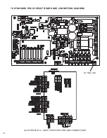
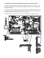
Page 21: ...Figure 13 Standard ED2 0 Circuit Board 21 ...
Page 22: ...22 Figure 14 Typical Outline 15 5 kV 1250 A ...
Page 23: ...23 Figure 15 Typical Outline 15 5 kV 2000 3000 3700 A and 27 kV 1250 2000 A ...
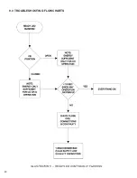
Page 40: ...40 9 0 TROUBLESHOOTING FLOWCHARTS ILLUSTRATION 5 READY LED CONTINUALLY FLASHING ...
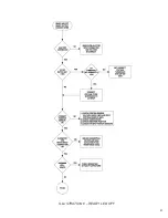
Page 41: ...41 ILLUSTRATION 6 READY LED OFF ...
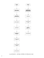
Page 42: ...42 ILLUSTRATION 7 CB WILL EITHER NOT OPEN OR CLOSE ...
Page 50: ...NOTES 50 ...
Page 51: ...NOTES 51 ...

