36
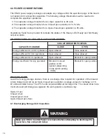
6.0 POWER CONSIDERATIONS
The ED2.0 power supply recharge unit adapts any voltage within the specified range of the board
to maintain 80 V across the capacitors. The following voltage thresholds must be reached to
complete the specified operations:
1. The capacitor voltage threshold for an Open operation is 49 volts.
2. The capacitor voltage threshold for a Close-Open operation is 72.5 volts.
3. The capacitor voltage threshold for a Open-Close-Open operation is 78 volts.
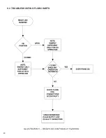
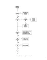
Illustrations 5 and 6 are provided to indicate the states of the Ready LED, Ready and Not Ready
output contacts.
RECHARGE TIME
As with all energy storage devices, there is a recharge time required for operation of the breaker.
A fully charged unit will do an Open-Close-Open operation. Average values for recharge on 15
kV units are listed below. The 27 kV units require additional recharge time. The values shown are
minimums and will change as capacitor life and operation conditions vary.
Open-1.0 sec
Close-2.2 sec
Close-Open-3.4 sec
Open-Close-Open-5 sec
6.1 Discharging Storage Unit Capacitors
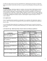
CB OPERATIONS VS AVAILABLE CAPACITOR CHARGE:
CIRCUIT BREAKER POSITION
CAPACITOR CHARGE
CLOSE
OPEN
Energy sufficient for O-CO operations
Open allowed
Close allowed
Energy sufficient for CO operations
Open allowed
Close allowed
Energy sufficient for O operations
Open allowed
Blocked in open position
Energy insufficient for any operation
Blocked in closed
Blocked in open position
position or CB
opened (depending
on dip switch setting
- I1004)
Make sure ED2.0 Control Power is removed before attempting to discharge the
capacitors. See paragraph below.
!
WARNING
Summary of Contents for R-MAG
Page 12: ...Figure 3 Interrupter Assembly 15 5 kV 1250 A 12 ...
Page 13: ...Figure 4 Interrupter Assembly 15 5 kV 2000 A 13 ...
Page 14: ...Figure 5 Interrupter Assembly 15 5 kV 3000 A 3700 FA 14 ...
Page 15: ...Figure 6 Interrupter Assembly 27 kV 1250 A 15 ...
Page 16: ...Figure 7 Interrupter Assembly 27 kV 2000 A 16 ...
Page 19: ...19 Figure 11 High Voltage Cabinet Layout 15 5 and 27 kV ...
Page 20: ...20 Figure 12 Typical Schematic Diagram ...
Page 21: ...Figure 13 Standard ED2 0 Circuit Board 21 ...
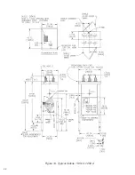
Page 22: ...22 Figure 14 Typical Outline 15 5 kV 1250 A ...
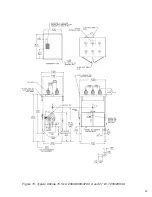
Page 23: ...23 Figure 15 Typical Outline 15 5 kV 2000 3000 3700 A and 27 kV 1250 2000 A ...
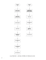
Page 40: ...40 9 0 TROUBLESHOOTING FLOWCHARTS ILLUSTRATION 5 READY LED CONTINUALLY FLASHING ...
Page 41: ...41 ILLUSTRATION 6 READY LED OFF ...
Page 42: ...42 ILLUSTRATION 7 CB WILL EITHER NOT OPEN OR CLOSE ...
Page 50: ...NOTES 50 ...
Page 51: ...NOTES 51 ...

