background image

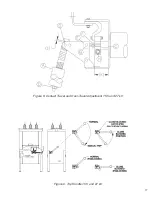
7. Support the moving contact of the vacuum interrupter at the contact block (C) and loosen the

nut (F) taking care not to apply any torque to the end of the vacuum interrupter as damage
may result. (Figures 8).

8. With the stem nut loose (F), install the shoulder pin and washers through the triangular bell-

cranks) to the bolt stem (B) (E) and fasten with the new locknut provided.   

9. Install the opposite end of the new bellcranks to the top of the pullrod (G) using the new "X"

type retaining washers provided and compress with pliers.

10. Torque the bolts and connections at (M) (N) per the torque specifications in section 9.0.8.

DO NOT TIGHTEN THE BOTTLE STEM NUT (F) ON THE VACUUM INTERRUPTER UNTIL
INSTRUCTED TO DO SO.   

11. Ensure that the locknut (F) on the bolt stem (E) is loose while supporting the moving contact

to prevent any torque from being exerted on the internal bellows of the vacuum interrupter.

12. Remove the shoulder bolt (B) while applying pressure from the back of the contact block.

Allow the contact block to move slowly to the closed position. Caution: Finger pinch point.

13. Loosen the pullrod locknut (D).
14. Turn the pullrod until the center of the hole for the shoulder bolt (B) is 1.687" from the con-

tact block (C). (This step sets a reference point for the bell cranks.)

15. Spin the bolt stem (E) until the shoulder bolt (B) can be inserted, then remove the shoulder

bolt (B). (This step establishes a reference from VI contact to the bell cranks.)

16. Spin the bolt stem (E) 6 to 6.5 full turns (6.5 turns is preferred final travel, but 6 is acceptable

prior to contact conditioning) clockwise. (This step sets the contact travel.)

17. Pull from back of contact block (C) until shoulder bolt (B) can be inserted.
18. Install a new locknut and tighten all hardware. Note: When tightening the nut (F) on the stem

bolt (E), support the moving contact at the contact block (C) to prevent any torque from
being exerted on the internal bellows of the vacuum interrupter as damage may result.

19. Do not reuse washers.
20. Operate the breaker a minimum of 200 times to season the new contacts, and then readjust

the breaker (Step 9-19). Proceed to section 9.3 for final adjustment.

9.3 Contact Travel and Over-Travel Adjustment 

(See Figure 8) (Control power required)

1. Measure travel and over-travel by opening and closing the breaker. Confirm the breaker is

within the limits below (by voltage rating). While the breaker is in the closed position, minor
adjustments can be made by loosening the nut (D) and rotating the pullrod (A). Make sure all
hardware is tightened before operating the breaker and proceed to step 2 below by your
breaker voltage rating.

2. Over-travel gaps (L) (produced at top of each pullrod while the breaker is in the closed posi-

tion) are recommended to be set from 0.170” to 0.260" (when measuring breakers in opera-
tion, it is acceptable to be 0.125”). 

3. Travel limits (K) (difference in measurements between contact block in open and closed posi-

tion) are:
For 15.5 kV breakers = 0.413" to 0.492" (10.5 mm - 12.5 mm).
For 27 kV breakers = 0.591" to 0.630" (15.0 mm - 16.0 mm). 

11

Summary of Contents for R-MAG

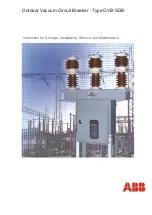
Page 1: ...Instruction Manual 15 5 kV 1250 2000 3000 3700 A 27 kV 1250 2000 A R MAG Medium Voltage Outdoor Dead Tank Vacuum Magnetic Circuit Breaker 1VAL255101 MB Rev D replaces IB 38 929M 15A ...

Page 2: ...ate 3 Figure 2 Lifting Detail 5 Figure 3 Interrupter Assembly 15 5 kV 1200 A 12 Figure 4 Interrupter Assembly 15 5 kV 2000 A 13 Figure 5 Interrupter Assembly 15 5 kV 3000 3700 A 14 Figure 6 Interrupter Assembly 27 kV 1250 A 15 Figure 7 Interrupter Assembly 27 kV 2000 A 16 Figure 8 Contact Travel and Over Travel Adjustment 17 Figure 9 Trip Handle 15 5 and 27 kV 17 Figure 10 Contact Erosion Graphs 1...

Page 3: ...ience in the safety procedures for this device WARNING Detailed descriptions of standard repair procedures safety principles and service operations are not included It is important to note this document contains some warnings and cautions against some specific service methods that could cause personal injury to service personnel damage equipment or render it unsafe These warnings do not cover all ...

Page 4: ...equest an inspection report File a formal claim with the carri er supported with paid freight bill inspection report and invoice The local ABB Sales Office must be notified This must be done within 10 days of receipt or receiver assumes all responsibility for damage 3 1 Receiving Inspection Upon receipt it is important to inspect promptly to be certain that the correct material has been received I...

Page 5: ...nge pins The position indica tor is visible through the front door The breaker nameplate showing rating information serial number and shop order number is mounted on the right hand side of the housing 4 3 Phase Assembly Figure 3 shows the details of the phase assembly The back bus work is attached directly to the fixed contact stud on the back end of the vacuum interrupter The current transfer ass...

Page 6: ...eadings are made on each phase of the breaker using a Biddle Ductor Typical values do not exceed 150 micro ohms 5 Voltage Withstand The complete breaker is tested between live parts and tank across open contacts and between phases In compliance with ANSI C37 09 and IEC an AC dielectric with stand test at 50 kV 15 kV 60 kV 27 kV is performed Test duration is one minute 6 Wiring Insulation The termi...

Page 7: ...rce voltage the Ready light will not be illuminat ed 7 2 Vacuum Test Perform an over voltage test on each phase assembly to verify that there has been no loss of vac uum in transportation or handling Experience has shown that a vacuum interrupter with the vacu um seal intact will withstand 37 5 kVAC across the open contacts for one minute and the same vacuum interrupter open to normal atmosphere w...

Page 8: ...cted to the ground pad on the side sheet 8 3 Arrester Protection ABB recommends that surge arresters be properly applied in the substation 8 4 Control Power Supply the control power as indicated on the wiring diagram If 240 VAC is used verify the con nections for the heaters before applying power Check all terminal block connections for proper tightness For details of the overall control circuit r...

Page 9: ...e closed position Contact ero sion reduces the compression of the over travel spring which in turn increases the contact travel Total travel of the actuator is fixed See 9 3 for minor adjustments Contact wear can be visually inspected A line is scribed on the moving contact stem 0 08 from VI end guide When the line reaches the VI end guide replace vacuum interrupters See Figures 3 8 and Procedures...

Page 10: ...ff and locked out and stored energy capacitors discharged Removing the existing interrupter assemblies 1 Using pliers expand the X type retaining rings G at the top of the pullrod A and discon nect the pullrod from the triangle bellcranks Figure 8 2 Loosen hardware at the point where the bottom of the bushing studs attach to each end of the top of the interrupter bus assemblies M and remove hardwa...

Page 11: ...tact to the bell cranks 16 Spin the bolt stem E 6 to 6 5 full turns 6 5 turns is preferred final travel but 6 is acceptable prior to contact conditioning clockwise This step sets the contact travel 17 Pull from back of contact block C until shoulder bolt B can be inserted 18 Install a new locknut and tighten all hardware Note When tightening the nut F on the stem bolt E support the moving contact ...

Page 12: ...Figure 3 Interrupter Assembly 15 5 kV 1250 A 12 ...

Page 13: ...Figure 4 Interrupter Assembly 15 5 kV 2000 A 13 ...

Page 14: ...Figure 5 Interrupter Assembly 15 5 kV 3000 A 3700 FA 14 ...

Page 15: ...Figure 6 Interrupter Assembly 27 kV 1250 A 15 ...

Page 16: ...Figure 7 Interrupter Assembly 27 kV 2000 A 16 ...

Page 17: ...17 Figure 9 Trip Handle 15 5 and 27 kV Figure 8 Contact Travel and Over Travel Adjustment 15 5 and 27 kV ...

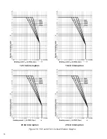
Page 18: ...18 Figure 10 15 5 and 27 kV Contact Erosion Graphs 12 5 kA Interruption 20 kA Interruption 16 kA Interruption 25 kA Interruption ...

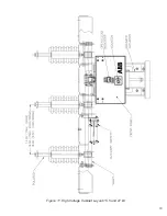
Page 19: ...19 Figure 11 High Voltage Cabinet Layout 15 5 and 27 kV ...

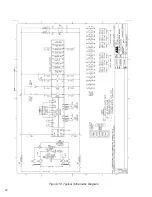
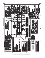
Page 20: ...20 Figure 12 Typical Schematic Diagram ...

Page 21: ...Figure 13 Standard ED2 0 Circuit Board 21 ...

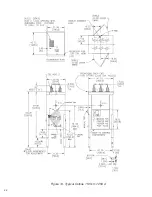
Page 22: ...22 Figure 14 Typical Outline 15 5 kV 1250 A ...

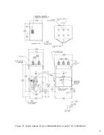
Page 23: ...23 Figure 15 Typical Outline 15 5 kV 2000 3000 3700 A and 27 kV 1250 2000 A ...

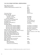
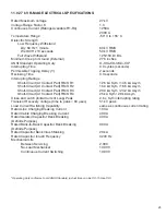
Page 24: ...it At Contact Part RMS R2 16 0 kA Sym 18 5 kA Asym Short Circuit At Contact Part RMS R3 20 0 kA Sym 23 2 kA Asym Short Circuit At Contact Part RMS R4 25 kA Sym 29 kA Asym Close and Latch Initial Current Loop Peak 2 6 x Sym interrupting rating Transient Recovery Voltage time to peak 36 μsec 29 kV peak Load Current Switching Capability same as continuous current rating Rated Line Charging Breaking C...

Page 25: ... Part RMS R2 16 0 kA Sym 18 5 kA Asym Short Circuit At Contact Part RMS R3 20 0 kA Sym 23 2 kA Asym Short Circuit At Contact Part RMS R4 25 kA Sym 29 kA Asym Close and Latch Initial Current Loop Peak 2 6 x Sym interrupting rating Transient Recovery Voltage time to peak 63 μsec 51 kV peak Load Current Switching Capability same as continuous current rating Rated Line Charging Breaking Current 100 A ...

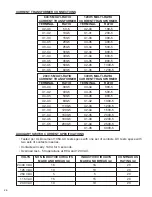
Page 26: ...NAL RATIO X3 X4 300 5 X3 X4 300 5 X1 X2 400 5 X4 X5 500 5 X4 X5 500 5 X3 X5 800 5 X2 X3 800 5 X1 X2 1000 5 X2 X4 1100 5 X2 X3 1200 5 X1 X3 1200 5 X2 X4 1500 5 X1 X4 1500 5 X2 X5 2000 5 X2 X5 1600 5 X1 X3 2200 5 X1 X5 2000 5 X1 X4 2500 5 X1 X5 3000 5 VOLTS NON INDUCTIVE CIRCUITS INDUCTIVE CIRCUITS CONTINUOUS MAKE AND BREAK A MAKE AND BREAK A RATING A 24 48 VDC 16 16 20 125 VDC 10 10 20 250 VDC 5 5 ...

Page 27: ...S TO 264 VOLTS KM10051 OPENING COMMANDS CAN OPENING COMMANDS CAN INCLUDES TRIP GO AS LOW AS 16 8 VDC GO AS LOW AS 16 8 VDC AND CLOSE AUXILIARY POWER 20 4 VOLTS TO 52 8 VOLTS 85 VOLTS TO 264 VOLTS AC KM10031 AUXILIARY POWER 16 8 VOLTS TO 75 VOLTS 77 VOLTS TO 280 VOLTS DC KM10031 1 The threshold for the binary inputs occurs at approximately 18 VDC or 19 VAC The threshold for the protec tion relay in...

Page 28: ...28 APPENDIX A INSTALLATION MAINTENANCE INSTRUCTIONS R MAG Medium Voltage Vacuum Power Circuit Breaker ED2 0 MAGNETIC ACTUATOR CONTROL BOARD ...

Page 29: ...4 Pins 7 8 33 4 5 Unit Ready KM1004 Pins 9 10 33 4 6 Unit Not Ready KM1004 Pins 11 12 33 4 7 Circuit Breaker Remote Open KM1004 Pins 13 14 33 5 0 FEATURES 35 5 1 Temperature Protection 35 5 2 Actuator Close and Trip Coil Continuity Monitor 35 5 3 Wrong Position Auto Trip 35 5 4 Energy Failure Auto Trip 35 5 5 Reduced Power Consumption 35 5 6 RS 232 Port JTAG Communication Port 35 6 0 POWER CONSIDE...

Page 30: ...ng an open or close command The Capacitor Storage Unit consists of two 0 1 farad Aluminum Electrolytic capacitors connected in parallel to provide a total capacitance of 0 2 farad on the 15 kV rating The Capacitor Storage Unit consists of three 0 1 farad Aluminum Electrolytic capacitors connected in parallel to provide a total capacitance of 0 3 farad on the 27 kV rating The energy stored is appro...

Page 31: ...y six of them are used for the R MAG breaker channel 5 is not used 3 1 Remote Close KM1005 CH 1 Pins 1 and 2 The Remote Close input is used to close the breaker remotely The input impedance is approxi mately 14 kOhms 3 2 Remote Open KM1005 CH 2 Pins 3 and 4 The Remote Open input is used to trip breaker remotely The input impedance is approximately 14 kOhms When tripping with electromechanical rela...

Page 32: ...y closed When the circuit breaker is tripped by operating the manual trip handle the breaker will go into the Open Lock mode This prevents any future closings until the Trip Handle is returned to the Normal Position The Manual Trip Handle must be left in the down position for the switch to remain open i e locked open It is important that the handle be moved all the way to the bot tom of the trip p...

Page 33: ...eaker is in the Closed position 4 3 Circuit Breaker Auxiliary Open KM1004 Pins 5 and 6 The Circuit Breaker Auxiliary Open contacts which close whenever the breaker is in the Open position 4 4 Circuit Breaker Auxiliary Closed KM1004 Pins 7 and 8 Additional set of normally open contacts which close whenever the breaker is in the Close posi tion 4 5 Unit Ready KM1004 Pins 9 and 10 These contacts are ...

Page 34: ...Capacitance 1 5 pF TIMING CHARACTERISTICS Maximum Actuating Time 5 0 milliseconds Maximum Releasing Time 3 0 milliseconds INSULATION Between Contacts and Coil 4000 Vrms 50 Hz 1 min Between Open Contact 1000 Vrms 50 Hz 1 min Resistance Roff 1000 Megohms at 500 VDC ENVIRONMENTAL CHARACTERISTICS Operating Temperature Range 50 to 55 Degrees C Storing Temperature Range 40 to 55 Degrees C Expected conta...

Page 35: ...s Necessary precautions must be taken when power is removed e g power removed for maintenance as the breaker will automatically trip if I1004 1 is in the On position 5 5 Reduced Power Consumption The Reduced Power Consumption setting will lower the power output of the power supply recharge unit on the ED2 0 board from 75 W power to 33 W This enables the ED2 0 board to be supplied with the energy d...

Page 36: ...d unit will do an Open Close Open operation Average values for recharge on 15 kV units are listed below The 27 kV units require additional recharge time The values shown are minimums and will change as capacitor life and operation conditions vary Open 1 0 sec Close 2 2 sec Close Open 3 4 sec Open Close Open 5 sec 6 1 Discharging Storage Unit Capacitors CB OPERATIONS VS AVAILABLE CAPACITOR CHARGE C...

Page 37: ...ed every 15 years for tropical cli mates and 20 years for an average yearly temperature in the outdoor breaker enclosure of less than 122 F 6 3 Breaker Ready Not Ready Binary Output Contacts and Ready Light Status CIRCUIT BREAKER POSITION CONDITION CLOSE OPEN Capacitor Energy sufficient Ready LED on Ready LED on For O CO operations Ready contact closed Ready contact closed Not ready contact opened...

Page 38: ...38 7 0 STANDARD ED2 0 CIRCUIT BOARD AND CONNECTING DIAGRAM ILLUSTRATION 3 ED2 0 CIRCUIT BOARD AND CONNECTIONS 1 2 3 4 5 6 1 2 3 4 5 6 On filter card ...

Page 39: ...UV delay time 1 2 3 4 Energy failure Auto Trip Enabled ON Energy failure Auto Trip Disabled OFF UV Disabled OFF OFF OFF UV Delay 500 ms OFF ON OFF UV Delay 1000 ms ON ON OFF UV Delay 2000 ms OFF OFF ON UV Delay 3000 ms ON OFF ON UV Delay 4000 ms OFF ON ON UV Delay 5000 ms ON ON ON I1002 I1004 I1001 UV Threshold 1 2 3 220 240 VAC VDC OFF OFF OFF 100 127 VAC VDC ON OFF OFF 48 60 VAC VDC OFF ON OFF 2...

Page 40: ...40 9 0 TROUBLESHOOTING FLOWCHARTS ILLUSTRATION 5 READY LED CONTINUALLY FLASHING ...

Page 41: ...41 ILLUSTRATION 6 READY LED OFF ...

Page 42: ...42 ILLUSTRATION 7 CB WILL EITHER NOT OPEN OR CLOSE ...

Page 43: ...ge across the capacitors The Control Unit monitors binary inputs and outputs hardware and software configurations posi tion sensors capacitor charge and switches the FET circuit to connect the capacitor voltage to the magnetic actuator coils following an open or close command The Switching Box connects the FET circuit from the storage unit to the magnetic actuators B B 1 2 3 4 5 6 BLACK BLACK BROW...

Page 44: ... on terminals 1 to 3 on KM1001 3 Verify there is 80 VDC from KM1002 1 to 3 4 If correct voltage is applied and DC is not reading then the board needs to be replaced READY LIGHT IS ON Check proximity sensors located on top of the mechanism The metal guard will have to be removed prior to inspection When the sensor is properly positioned you will see a yellow light on the rear of the sensor for each...

Page 45: ...nd Blue is connected to ground When metal is placed in front of a sensor it will be picked up and you will see the yellow LED lit on the back of the sensor From the black wire to the blue wire verify it reads 18V When the metal is removed the voltage should drop to near 0 The Under Voltage UV function is enabled and input is open Inspect dip switch I1004 Ensure switches 2 3 4 and 5 are in the off ...

Page 46: ...his case only the closing operation is available open the circuit breaker the ready LED will be turned off and check the closing coil circuit Disconnect the magnetic actuator from the plug to the left of the mechanism There are two Phillips head screws that keep the plug held together The top two wires are red and the bottom two wires are blue The top red 43 and top blue 45 wire go to the Off open...

Page 47: ...ntrol board Ensure that there is 80 VDC across KM1002 terminals 1 and 3 The ready LED on control panel is off See conditions under Ready LED is off unit not ready The control panel is dam aged or not connected properly Verify the control panel 6 pin plug is plugged into KM1007 The energy in the capacitor bank is not enough for a CO operation Ensure the auxiliary supply voltage is connected See rea...

Page 48: ...efore proceeding discharge the capacitors by jumpering KM1003 pins 4 and 5 The time constant is 33 minutes A smaller external resistor can be used for a quicker discharge but the discharge current should be restricted to 10 amperes maximum This means that no lower than 10 ohms 25 watt external resistance should be used to perform capacitor dis charging When discharging with a external capacitor co...

Page 49: ...lug 8 Remove plug for push button plate This is not held by retainers 9 Remove four 250 20 nut lock and flat washer from the four corners Keep the three rubber washers behind each screw 10 250 Hex nut Rubber washer ILLUSTRATION 10 ED2 0 CONTROL BOARD PARTS AND MOUNTING ILLUSTRATION 10 ED2 0 CIRCUIT BOARD CONNECTORS ...

Page 50: ...NOTES 50 ...

Page 51: ...NOTES 51 ...

Page 52: ...y 2009 Rev D replaces IB 38 929M 15A ABB Inc 655 Century Point Lake Mary FL 32746 U S A For sales marketing contact your local representative or Tel 1 407 732 2000 1 800 929 7947 Fax 1 407 732 2161 www abb com mediumvoltage ...

Reviews: