background image

1SFC13105M0201      |   Service Manual   |   

Service PSTX720...840

           19

3.2 

Configuring the HMI 

This chapter describes how update firmware, set the ID 
and how to reset the Softstarter to default. 

3.2.1 

Update Firmware 

Firmware needs to be updated when changing the HMI. 
Please contact your ABB sales office for information.  

See Figure 1.    


3.2.2 

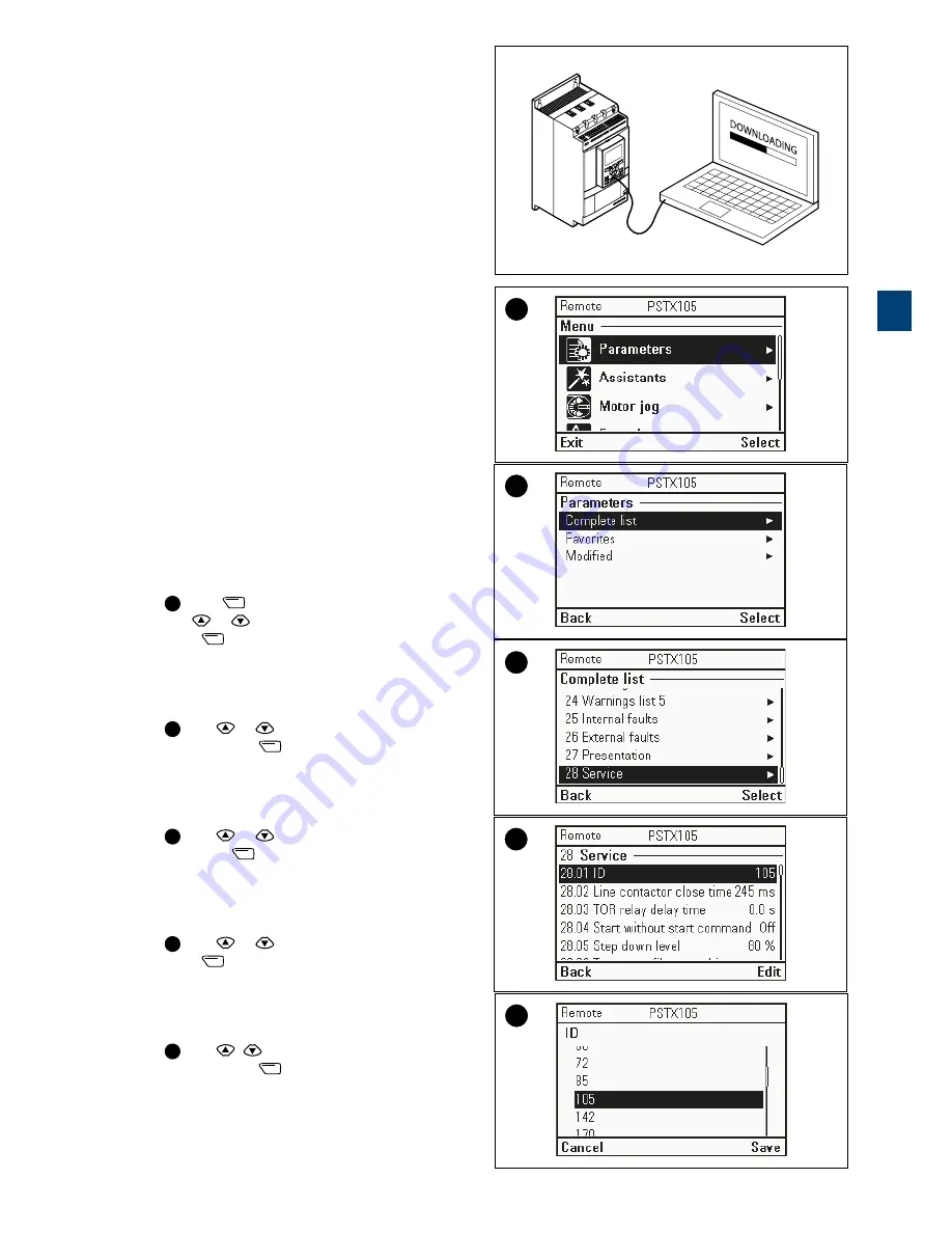
Set the ID 

The ID of the Softstarter has to be changed when the 
PCBA has been changed and after updating firmware.  
Choose between 720…840 due to type of Softstarter.

1. 

Switch on the power supply (terminal 1 and 2). 
 

2. 

1

 Press 

 ”Menu” to reach Menu. 

Use 

 or 

 to navigate to 

Parameters 

and then 

press 

 ”Select”. 


3. 

2

 Use  

 or 

 to navigate to 

Complete list 

and then press 

 ”Select”.  


4. 

3

 Use  

 or 

 to navigate to 

28


Service 

and 

then press 

 ”Select”. 


5. 

4

 Use  

 or 

 to navigate to 

28.01


ID 

and then 

press 

 ”Edit”.  


6. 

5

 Use  

 to set 

28.01


ID 

to 

105


and then press 

 ”Save”. 


1

3.2.1_1

1

2

3

4

5

3

Summary of Contents for PSTX 30***105

Page 1: ...Softstarter type PSTX720 840 Service manual Service manual en rev B 1SFC132115M0201 ...

Page 2: ...rs he is kindly asked to notify us as soon as possible The data contained in this manual is intended solely for the product description and is not to be deemed to be a statement of guaranteed properties In the interests of our customers we constantly seek to ensure that our products are developed to the latest technological standards As a result there may be some differences between the Softstarte...

Page 3: ...equipment or property WARNING Warning symbol indicates the presence of hazardous voltage which could result in personal injury Electrostatic sensitive devices warning Electrostatic discharge is needed to not damage the equipment WARNING HAZARDOUS VOLTAGE Symbol indicates that only authorized and appropriately trained personnel are allowed to do the installation operation and maintenance of the pro...

Page 4: ......

Page 5: ...1 1 3 5 2 4 1 Introduction 2 Description 3 Service PSTX720 840 4 Circuit Diagrams 5 Revisions Softstarter type PSTX720 840 Service manual ...

Page 6: ......

Page 7: ...3105M0201 Service Manual Introduction 7 1 1 1 Service manual 1 1 1 Intended audience 8 1 1 2 Revision notes and related documents 8 1 1 3 Acronyms and abbreviations 8 1 1 4 Chapters included 8 1 Introduction ...

Page 8: ...tenance shall be performed in accordance with this instruction to ensure product functionality and to prevent that the lifetime of the product is shortened 1 1 1 Intended audience General The service manual is intended for internal use and for the maintenance personnel responsible for service within ABB Reprint Reprinting of this service manual is only promoted on approval Reprint for internal use...

Page 9: ...e 10 2 1 2 Tools required 10 2 1 3 Service and repair 10 2 1 4 Weights 10 2 1 5 Dimension prints PSTX30 105 PSTX142 170 11 2 1 6 Dimension prints PSTX210 370 PSTX470 570 12 2 1 7 Dimension prints PSTX720 840 PSTX1050 1250 13 2 1 8 Markings and connections 14 2 1 9 Identification of Softstarter type 15 ...

Page 10: ...leaned of dirt and or dust on a regular basis The top of the Softstarter should be examined for evidence of water seepage The source of the water should be immediately identified and corrective measures taken to permanently correct the condition Check the By pass Contactor Inspect for loose broken or worn parts Examine for excessive wear of moving parts Observe that operating mechanisms function p...

Page 11: ... 6 in 3 mm 0 1 in 178 8 mm 7 in 13 mm 0 5 in 6x 119 mm 4 7 in 298 5 mm 11 7 in 7 5 mm 0 3 in 314 mm 12 4 in 258 mm 10 2 in 30 mm 1 2 in 4x Ø14 2x 219 6 mm 8 6 in 238 3 mm 9 3 in 377 mm 14 8 in 165 mm 6 5 in 7 5 mm 0 3 in 360 5 mm 14 1 in 199 mm 7 8 in 35 mm 1 3 in 4x 6 6 mm 0 2 in 4x 303 mm 11 9 in 107 6 mm 4 2 in 5 mm 0 2 in 17 5 mm 0 7 in 6x Ø18 2x 2 ...

Page 12: ...in 451 2 mm 17 7 in 10 5 mm 0 4 in 389 mm 15 3 in 5 mm 0 2 in 151 mm 5 9 in Ø18 2x 200 mm 7 9 in 258 mm 10 2 in 43 7 mm 1 7 in 4x 19 6 mm 0 8 in 6x 361 mm 14 2 in 282 15 mm 11 1 in 262 82 mm 10 3 in 6 mm 0 2 in 6x 58 2 mm 2 3 in 6x 25 mm 0 9 in 6x 336 mm 13 2 in 2x 460 mm 18 1 in 63 mm 2 5 in 4x 493 mm 19 4 in 466 mm 18 3 in 9 mm 0 3 in 7 mm 0 2 in 4x Ø13 4x 2 ...

Page 13: ... mm 19 29 in 408 9 mm 16 1 in 460 mm 18 11 in 493 mm 19 409 in 40mm 1 57 in 72 mm 2 8 in 7 mm 0 276 in 4x 7 mm 0 276 in 4x 369 mm 14 5 in 565 mm 22 2 in 515 mm 20 2 in 485 mm 19 in 435 mm 17 1 in 62 6 mm 2 46 in 6x 8 mm 0 3 in 6x 367 mm 14 4 in 150 mm 5 9 in 2x Connection bars for PSTX1050 407 mm 16 in 50 mm 1 9 in 6x 40 mm 1 5 in 6x 133 5 mm 5 2 in 2x 72 mm 2 8 in 4x 301 5 mm 11 8 in 22 5 mm 0 8 ...

Page 14: ... 5 1 4 6 2 1 Stop L 100 250V 50 60 Hz K4 K5 K6 Start Stop In1 In2 DGND 24V GND N In0 Ready Run Fault Protection PSTX Symbol for Torque control Anybus connection Com2 Supply voltage Us Order code Technical data according to UL 508 Fieldbus connection Com1 Motor side connection Terminal marking of control circuits Line side connection Display Keypad Mini USB Country of origin Utilization code Approv...

Page 15: ...rial number C Serial number information The ABB Serial number within business unit Control Products has the following structure Table 5 Prefix Register Id Individual identity number part 1S 160 PPPP YY WW NNNN Prefix Defined in ABB Corporate Standard 9AAK100359 Register Id Defined in BAATLV Instruction 1SFD2000 8 Individual identity number part PPPP Identification for product type part of product ...

Page 16: ...16 Description Service Manual 1SFC13105M0201 2 ...

Page 17: ...ain power cables and the control cables 23 3 3 4 Connect the main power cables and the control cables 24 3 4 Service of the PCBA 3 4 1 Change the PCBA 26 3 5 Change the Fans Bar holders and Current transformers 3 5 1 Change the Fans 30 3 5 2 Change the Bar holders 31 3 5 3 Change the Current transformers 33 3 5 4 Assemble the Softstarter 35 3 6 Change the Bypass contactor 3 6 1 Change the Bypass c...

Page 18: ...ss service parameters Follow this instruction in order to make the service parameters available on the Softstarter 1 Switch on the power supply terminal 1 and 2 2 1 Press Options to reach Options menu Use or to navigate to Configure HMI and then press Select 3 2 Use or to navigate to Enter service profile and then press Select 4 3 Use and to enter the service code Enter the following code 73758 an...

Page 19: ... The ID of the Softstarter has to be changed when the PCBA has been changed and after updating firmware Choose between 720 840 due to type of Softstarter 1 Switch on the power supply terminal 1 and 2 2 1 Press Menu to reach Menu Use or to navigate to Parameters and then press Select 3 2 Use or to navigate to Complete list and then press Select 4 3 Use or to navigate to 28 Service and then press Se...

Page 20: ... navigate to Settings and then press Select 3 2 Use or to navigate to Reset to defaults and then press Select 4 3 Use or to navigate to Reset all parameters and then press Select 5 4 Following message will appear on the display Continue to reset all parameters to their default values Press Yes to reset all parameters or No if you whish to cancel the operation 1 2 3 4 3 ...

Page 21: ...cs can be affected by damage caused by electrostatic discharge This can happen if a charged tool or person touches a component Therefore it is very important that all tools and personnel are discharged by touching an earthed point before the PCBA or any of the components are touched It is equally important to discharge the package with the new component before opening it A person walking on a carp...

Page 22: ...1 Connect RJ45 plug 1 Connect the RJ45 plug to its socket Make sure the plug gets properly connected listen for a clicking sound from the locking clip when mounting the plug 2 Place new HMI module 1 Place the new HMI module on top of the unit with the front end facing downwards and the rear end facing upwards 2 Dock the HMI module by pushing the rear end downwards and carefully snap the module int...

Page 23: ... prior to disconnecting them to enable proper re connection 1 Loosen the M3 screws using a slotted screwdriver and disconnect the control cables from the terminals 2 Mark main power cables Mark the power cables prior to disconnecting them 1 Mark the main power cables on the top terminals 1L1 3L2 and 5L3 with 1 3 and 5 2 Mark the main power cables on the bottom terminals 2T1 4T2 and 6T3 with 2 4 an...

Page 24: ...D damage to the Softstarter 1 Connect main power cables 1 Fasten the main power cables according to previously made markings 1 3 or 5 to top terminals 1L1 3L2 and 5L3 Hexagon no 8 M10x30 28Nm Washers and square nuts to be used 2 Fasten the main power cables according to previously made markings 2 4 or 6 to bottom terminals 2T1 4T2 and 6T3 Hexagon no 8 M10x30 28Nm Washers and square nuts to be used...

Page 25: ...appen if a charged tool or person touches a component Therefore it is very important that all tools and personnel are discharged by touching an earthed point before the PCBA or any of the components are touched It is equally important to discharge the package with the new component before opening it A person walking on a carpet can be charged with up to fifteen thousand volt 15000V Compare this wi...

Page 26: ...t still mounted on bracket to facilitate continued service 2 Disconnect SCR cables from PCBA Mark the SCR cables with 1 2 3 prior to disconnecting them to ensure proper re connection Note that markings are to be made in accordance with existing data available on the PCBA bracket 1 Disconnect the three SCR cables from their terminals on the PCBA using a long nose plier 2 Pull out the three SCR cabl...

Page 27: ...expended PCBA 6 Place new PCBA on PCBA bracket Note that rubber bushings shall be mounted on the PCBA prior to assembly 1 Position the bracket so that ABB s logotype appears upside down on the upper end 2 Place the new PCBA on the bracket by sliding it onto bracket from the right direction until attached to the peg in the lower left corner 3 Gently press the PCBA onto the bracket peg in the upper ...

Page 28: ...he PCBA 10 Place new PCBA and PCBA bracket 1 Place the new PCBA mounted to bracket on the unit Make sure cables do not get stuck in between the bracket frame and Softstarter when mounted 11 Place HMI cover Place the HMI cover on the unit and align it to the plastic screw sleeves located on lower housing 1 Fasten the HMI cover with 4x Torx 20 M4x12 1 6Nm 2 Fasten 1x Torx 15 M3 5x12 0 5 Nm on the HM...

Page 29: ...en if a charged tool or person touches a component Therefore it is very important that all tools and personnel are discharged by touching an earthed point before the PCBA or any of the components are touched It is equally important to discharge the package with the new component before opening it A person walking on a carpet can be charged with up to fifteen thousand volt 15000V Compare this with ...

Page 30: ...with two screws per fan Dispose of expended fans 3 Fasten new fans to fan cover Note that fans are to be mounted with regards to air flow directions 1 Fasten 8x Torx 20 M4x12 1 3Nm to attach the four fans on the fan cover Screws are to be mounted diagonally with two screws per fan 4 Place fan cover 1 Thread the fan cables through the cable inlets 2 Fasten the fan cover to the unit with 10x Torx 20...

Page 31: ...oves when working with cover plates to prevent cutting injuries 1 Remove fan cover 1 Loosen 10x Torx 20 M4x8 from the fan cover 2 Pull the fan cover outwards from unit with the fans still mounted to fan cover 2 Remove top cover 1 Loosen 10x Torx 20 M4x8 and pull the top cover outwards from unit 3 Remove front and side covers 1 Remove the front cover by lifting it upwards from unit 2 Remove the sid...

Page 32: ...ing bar holders If needed Dismantle assemble current transformers from to the Softstarter as described in chapter 3 5 3 6 Place new bottom side bar holder 1 Place the new bar holder onto phase bars 7 Fasten screws to bottom bar holder 1 Fasten 2x Torx 30 M6x16 8Nm to the lower corners of the bar holder 2 Fasten 6x Torx 30 M6x16 8Nm to attach the bar holder to the phase bars REASSEMBLE THE SOFTSTAR...

Page 33: ...rify the ratio according to Table 7 below Make sure cable of new current transformer gets connected in accordance to previously made markings 2 Position the new current transformer with the cable facing upwards and the current direction arrow facing towards the bar holder Slide the current transformer onto the middle phase bar 4 Place bottom bar holder 1 Place the bar holder onto phase bars and fa...

Page 34: ...g to Table 7 below Make sure cable of new current transformer gets connected in accordance to previously made markings 2 Position the new current transformer with the cable facing upwards and the current direction arrow facing towards the bypass contactor Slide the current transformer onto outer phase bar 8 Place top bar holder 1 Place the bar holder onto phase bars and fasten 2x Torx 30 M6x16 8Nm...

Page 35: ...lock to rails 3 Thread the cables through the cable inlets opening in the front cover 10 Place fan cover 1 Thread the fan cables through the cable inlets 2 Fasten the fan cover to the unit with 10x Torx 20 M4x8 2 9Nm 11 Place top cover 1 Fasten the top cover to the unit with 10x Torx 20 M4x8 2 9Nm REASSEMBLE THE SOFTSTARTER Place PCBA cables and HMI cover Place the PCBA connect all cables and inst...

Page 36: ...hes a component Therefore it is very important that all tools and personnel are discharged by touching an earthed point before the PCBA or any of the components are touched It is equally important to discharge the package with the new component before opening it A person walking on a carpet can be charged with up to fifteen thousand volt 15000V Compare this with the fact that some sensitive compon...

Page 37: ...oves when working with cover plates to prevent cutting injuries 1 Remove fan cover 1 Loosen 10x Torx 20 M4x8 from the fan cover 2 Pull the fan cover outwards from unit with the fans still mounted to fan cover 2 Remove top cover 1 Loosen 10x Torx 20 M4x8 and pull the top cover outwards from unit 3 Remove front and side covers 1 Remove the front cover by lifting it upwards from unit 2 Remove the sid...

Page 38: ...top and bottom bar holders 1 Loosen in total 4x Torx 30 M6x16 from the lower corners of the bar holders 2 Pull the bar holders including phase bars outwards from unit and remove the square nuts 6 Remove screws from cooling towers 1 Loosen 6x Torx 25 M5x16 to disengage the cooling towers from base plate 7 Remove cooling towers 1 Lift off all three cooling towers from base plate Hexagon n 10 M12x40 ...

Page 39: ...move bypass contactor 1 Remove the bypass contactor from base plate Dispose of expended bypass contactor 9 Place new bypass contactor 1 Place the new bypass contactor on the base plate with terminals 2T1 4T2 and 6T3 facing downwards 8 3 6 1_8 1 9 3 6 1_9 1 3 ...

Page 40: ...g tower 3 To be placed on the lower right side of the base plate and have three drill holes on the internal phase bar 2 Fasten cooling towers 1 Fasten cooling towers to base plate with 6x Torx 25 M5x16 2 9Nm 2 Fasten the bypass contactor to base plate with 4x Hexagon no 5 M5x100 5Nm 3 Fasten phase screws 1 Place the square nuts with the angled sides inwards and slightly tighten 6x Hexagon no 10 M1...

Page 41: ...s opening in the front cover 6 Place fan cover 1 Thread the fan cables through the cable inlets 2 Fasten the fan cover to the unit with 10x Torx 20 M4x8 2 9Nm 7 Place top cover 1 Fasten the top cover to the unit with 10x Torx 20 M4x8 2 9Nm REASSEMBLE THE SOFTSTARTER Place PCBA cables and HMI cover Place the PCBA connect all cables and install the HMI cover as described in chapter 3 4 1 step 6 11 C...

Page 42: ...ortant that all tools and personnel are discharged by touching an earthed point before the PCBA or any of the components are touched It is equally important to discharge the package with the new component before opening it A person walking on a carpet can be charged with up to fifteen thousand volt 15000V Compare this with the fact that some sensitive components can be destroyed when discharged on...

Page 43: ... when working with cover plates to prevent cutting injuries 1 Remove fan cover 1 Loosen 10x Torx 20 M4x8 from the fan cover 2 Pull the fan cover outwards from unit with the fans still mounted to fan cover 2 Remove top cover 1 Loosen 10x Torx 20 M4x8 and pull the top cover outwards from unit 3 Remove front and side covers 1 Remove the front cover by lifting it upwards from unit 2 Remove the side co...

Page 44: ...he bar holder 2 Loosen 3x Hexagon no 10 M12x40 and pull the bar holders including phase bars outwards from unit and remove the square nuts 6 Remove phase bars from cooling tower 1 Loosen 4x Torx 30 M6x16 and remove the internal phase bar from cooling tower 2 Loosen 2x Torx 30 M6x16 to separate cooling tower from the internal phase bar 7 Remove screw nuts and tension bars from cooling tower 1 Loose...

Page 45: ...lift the SCR by the wire Ensure there is no damage to the welding flange or to the contact surface 9 Preparation of heat sink and SCR Clean all polished contact surfaces carefully with Ethanol Use well moistened lint free paper Avoid contact with surface Lubricate directly after polishing cleaning within 5 minutes The contact surfaces must be dry before lubrication Apply a couple of drops of silic...

Page 46: ...SCR unit and middle heat sink onto stud bolts on cooling tower Align to guide pins 3 Place the upper SCR unit and upper heat sink onto stud bolts on cooling tower Align to guide pins 2 Place tension bars and screw nuts to cooling tower 1 Place the spacing bar onto stud bolts on cooling tower 2 Place the two torque washers and tension bars onto stud bolts on cooling tower 3 Place 2x Hexagon no 16 M...

Page 47: ...e may not be more than 2 mm See figure below 7 Place side and front covers Make sure to position side covers with dual locking rails facing upwards prior to assembly 1 Interlock the side covers to rails and slide them sideways into position Attach side covers to support brackets mounted on cooling towers 2 Place the front cover on the unit and interlock to rails 3 Thread the cables through the cab...

Page 48: ...9Nm REASSEMBLE THE SOFTSTARTER Place PCBA cables and HMI cover Place the PCBA connect all cables and install the HMI cover as described in chapter 3 4 1 step 6 11 Connect main power cables and control cables Connect the main power cables and the control cables as described in chapter 3 3 4 step 1 2 Tx 20 M4 x 8 2 9Nm 9 3 7 2_9 1 3 ...

Page 49: ...of electronics can be affected by damage caused by electrostatic discharge This can happen if a charged tool or person touches a component Therefore it is very important that all tools and personnel are discharged by touching an earthed point before the PCBA or any of the components are touched It is equally important to discharge the package with the new component before opening it A person walki...

Page 50: ...A from unit at this point still mounted on bracket to facilitate continued service 2 Disconnect SCR cables from PCBA Mark the SCR cables with 1 2 3 prior to disconnecting them to ensure proper re connection Note that markings are to be made in accordance with existing data available on the PCBA bracket 1 Disconnect the three SCR cables from their terminals on the PCBA using a long nose plier 2 Pul...

Page 51: ...e inlets on the PCBA bracket 2 Connect the three SCR cables according to previously made markings 1 2 or 3 to their terminals on the PCBA 7 Place HMI cover 1 Place back the PCBA and the bracket in the Softstarter Make sure cables do not get stuck in between the bracket frame and Softstarter when mounted Place the HMI cover on the unit and align it to the plastic screw sleeves located on lower hous...

Page 52: ...y damage caused by electrostatic discharge This can happen if a charged tool or person touches a component Therefore it is very important that all tools and personnel are discharged by touching an earthed point before the PCBA or any of the components are touched It is equally important to discharge the package with the new component before opening it A person walking on a carpet can be charged wi...

Page 53: ...rter to the right 2 Loosen 2x Torx 30 M6x12 and remove the left stays 3 Loosen 2x Torx 30 M6x12 and remove the right stays 2 Place stays 1 Place the new left stays on the Softstarter and fasten with 2x Torx 30 M6x12 8Nm 2 Place the new right stays on the Softstarter and fasten with 2x Torx 30 M6x12 8Nm 3 Rotate the Softstarter to the left REASSEMBLE THE SOFTSTARTER Connect main power cables and co...

Page 54: ...54 Service PSTX720 840 Service Manual 1SFC13105M0201 3 ...

Page 55: ...1SFC13105M0201 Service Manual Circuit Diagrams 55 4 4 Circuit Diagrams 4 1 Circuit diagram PSTX 4 1 1 Circuit diagram PSTX30 PSTX1250 IEC version 56 4 1 2 Circuit diagram PSTX30 PSTX1250 UL version 56 ...

Page 56: ...s 23 24 25 26 27 28 2 1 29 30 Anybus External control voltage 24V DC 18 13 14 Stop Start M U V W 2T1 4T2 6T3 1L1 3L2 5L3 V5 V6 K2 V4 V3 V2 V1 Ct1 Ct2 Ct3 2T1 1L1 K5 K4 12 11 10 9 8 7 6 5 4 K6 3 Only on PSTX470 PSTX1250 4T2 3L2 6T3 5L3 4 1 2 Circuit diagram PSTX30 PSTX1250 UL version A C B INCOMING LINES CXFU CHFU CCT CHFU START STOP 20 21 19 18 16 17 15 22 28 29 30 24 23 13 14 2 1 L N GND Start St...

Page 57: ...1SFC13105M0201 Service Manual Circuit Diagrams 57 4 ...

Page 58: ...anual 1SFC13105M0201 The following revisions is done on this document Table 5 Document number Revision Chapter Description Date 1SFC132115M0201 A First release 2015 12 18 1SFC132115M0201 B 3 Updates 2017 06 30 5 5 Revisions ...

Page 59: ...1SFC13105M0201 Service Manual Revisions 59 5 ...

Page 60: ...ion subject to change without notice ABB AB Control Products Low voltage Products SE 721 61 Västerås Sweden Telephone 46 0 21 32 50 00 www abb com lowvoltage Softstarter Type PSTX720 840 Service Manual 1SFC132115M0201 rev B 2017 06 30 ABB AB Control Products ...

Reviews: