


Operation Manual / Power2 650-M / 4.2 High-pressure stage
Figures
© Copyright 2019 ABB. All rights reserved.
HZTL4066_EN
Revision A
March 2019
Figures
Fig. 1: Removing the high-pressure stage................. 4
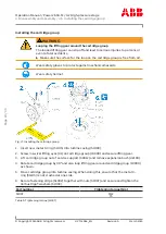
Fig. 2: Loosening the clamping nut ............................. 5
Fig. 3: Removing the high-pressure stage ................ 6
Fig. 4: Gaskets in the slots of the bearing casing..... 7
Fig. 7: Steps for fastening the high-pressure stage ...
10
Fig. 9: Tightening pressure screws............................ 12
Weights of the assemblies .............................. 17
Fig. 11: Removing the compressor casing ................ 18
Fig. 12: Oil orifice in the bearing casing .................... 19
Fig. 13: Removing the cartridge group..................... 20
Fig. 14: Removing the nozzle ring............................... 21
Fig. 15: Nozzle ring compression PD.......................... 22
Fig. 16: Installing the nozzle ring ................................ 23
Fig. 17: Installing the cartridge group ...................... 24
Fig. 18: Installing the compressor casing................ 25
Fig. 19: Measuring clearances N and R ..................... 26
Fig. 20: Measuring clearance A and B ........................ 27
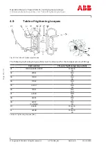
Fig. 21: Overview of tightening torques .................. 28
Fig. 22: Attaching the cover plate .............................. 31
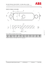
Fig. 23: Cover plate drawing........................................ 32
Fig. 24: Figure for cover plate, slots for O-rings ..... 33
Fig. 25: High-pressure stage with part numbers ... 36
Page
38
/
39
Page
38
/
39


