background image


PositionMaster EDP300

 DIGITAL POSITIONER  |  OI/EDP300-EN REV. D 

79


14


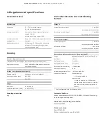
Supplemental specifications 

Actuator travel 


Rotation angle 

Used range 

25 … 270° for rotary actuator 
25 … 60° for linear actuator 

Actuator travel limit 

Min. and max. limits, freely configurable in 
range 0 ... 100 % 
Actuator travel (min. range > 20% 

Actuator travel time 
prolongation 

Range of 0 ... 200 seconds, separately for each 
direction 

Dead band time limit 

Setting range 0 ... 200 seconds (monitoring 
parameter for control until the deviation 
reaches the dead band) 


Housing 


Material / Degree of protection 

Aluminum with 

á

 0.1% copper  Optional stainless steel 1.4404 (316L) 

Degree of protection 

IP 65 / NEMA 4X (NEMA 4X does not permit 
overhead mounting) 


Surface / color (aluminum housing only) 

Dipping varnish 

With epoxy resin, stove-hardened 

Housing varnished black 

RAL 9005 
RAL 9002 


Weight 

Aluminum 

2.4 kg (5.29 lb) 

Stainless steel 1.4404 (316L) 

5.5 kg (12.13 lb) 


Mounting orientation 

Any 


Transmission data and contributing 

factors 


Output Y1 

Increasing set point signal 

0 to 100 %

Increasing pressure at output

Decreasing set point signal 

0 to 100 %

Decreasing pressure at output


Action (set point signal) 

Increasing set point 

4 to 20 mA

= actuator position 0 to 100 %

Decreasing set point 

20 to 4 mA

= actuator position 0 to 100 %


Characteristic curve (actuator travel = f {set point signal}) 

Linear 

Equal percentage 1:25 or 1:50 or 25:1 or 50:1* 

Deviation 

< 0.5 % 

Configurable zone 

0 to 100 %, 

Configurable dead zone 

0.1 to 10 %, 

Resolution (AD-conversion) 

> 16,000 steps 

Sampling frequency 

20 ms 

Ambient temperature effect 

< 0.5 % for each 10 K 

Influence of vibration 

Standard design: 

< 1 % to 10 g and 80 Hz 

Marine version: 

< 1 % to 4 g and 100 Hz – EDP300 and 

remote design (control unit) < 1 % to 10 g 
and 100 Hz for remote design (position 
sensor) 

*  freely configurable with 20 reference points 


Seismic vibration 

Meets requirements of DIN / IEC


60068-3-3 Class III for strong 

and strongest earthquakes. 
 

Influence of mounting orientation 

Not measurable. 
 

Noise emissions 

Max. 100 db (A) 
Noise-reduced version max. 85 db (A)  


Summary of Contents for PositionMaster EDP300

Page 1: ...nd offers an outstanding price performance ratio Fully automatic determination of the control parameters and adaptation to the positioner allow for considerable time savings as well as optimum control behavior Due to its characteristics the positioner is suited for even the most demanding operating conditions Additional Information Additional documentation on PositionMaster EDP300 is available for...

Page 2: ...ple of operation 14 5 Product identification 14 Name plate 14 6 Transport and storage 15 Inspection 15 Transporting the device 15 Storing the device 15 Ambient conditions 15 Returning devices 15 7 Installation 15 Safety instructions 15 External position sensors 16 Mechanical mounting 17 General 17 Mounting on linear actuators 18 Mounting on control valves 21 Mounting on rotary actuator 21 Electric...

Page 3: ...sy Setup 50 Menu Device Setup 52 Menu Display 58 Menu Controller 59 Menu Input Output 62 Menu Communication 68 Menu Diagnosis 69 Menu Device Info 71 Menu Service 72 10 Diagnosis error messages 74 Calling up the error description 74 Possible error messages 75 11 Maintenance 78 12 Repair 78 Returning devices 78 13 Recycling and disposal 78 14 Supplemental specifications 79 Actuator travel 79 Housing...

Page 4: ...he product may only be performed if expressly permitted by these instructions Information and symbols on the product must be observed These may not be removed and must be fully legible at all times The operating company must strictly observe the applicable national regulations relating to the installation function testing repair and maintenance of electrical products Warnings The warnings in these...

Page 5: ...n the product and your network or any other network as the case may be Operator shall establish and maintain any appropriate measures such as but not limited to the installation of firewalls application of authentication measures encryption of data installation of anti virus programs etc to protect the product the network its system and the interface against any kind of security breaches unauthori...

Page 6: ...persons whose training has included instructions on different types of protection and installation techniques concerned rules and regulations as well as general principles of zoning The person must possess the appropriate competences for the type of work to be conducted When operating with combustible dusts comply with EN 60079 31 The safety instructions for electrical apparatus in potentially exp...

Page 7: ...he housing must not be opened Only use cable glands which are approved for the type of protection and correspond to IP rating â IP 6X Danger due to propagating brush discharge must be avoided Operation in temperature class T6 During operation in temperature class T6 when the equipment is partially or fully depressurized ensure that there is no possibility of a hazardous atmosphere getting into the...

Page 8: ...Option modules Module for the emergency shutdown function Terminals 85 Æ86 Temperature class T1 T6 Ui 30 V Pi 1 W Ci 5 3 nF Li negligibly small Module for analog feedback AO Terminals 31 Æ32 Temperature class T1 T4 Temperature class T6 Ui 30 V Ui 28 V Ii 320 mA Ii 320 mA Pi 1 W Pi 0 8 W Ci 11 3 nF Li 150 μH Module for universal input UAI Terminals 21 Æ22 Temperature class T1 T4 Temperature class T...

Page 9: ...y shutdown function Terminals 85 Æ86 Electrical values UN á 30 V Module for analog feedback AO Terminals 31 Æ32 Electrical values IN á 22 mA UN á 30 V Module for universal input UAI Terminals 21 Æ22 Electrical values IN á 22 mA Umax á 30 V Module for digital feedback SW1 SW2 Terminals SW 1 41 Æ42 SW 2 51 Æ52 Electrical values Per output UN á 30 V Limit switch Limit 1 Limit 2 Limit monitor with pro...

Page 10: ... II Div 2 Gr E F G T4 or T6 CL III Div 2 T4 or T6 Class I Zone 2 AEx nA IIC T4 or T6 T4 Ta Æ40 to 85 C Æ40 to 185 F T6 Ta Æ40 to 40 C Æ40 to 104 F IP64 Mounting The installation commissioning maintenance and repair of devices in areas with explosion hazard must only be carried out by appropriately trained personnel The operator must strictly observe the applicable national regulations with regard ...

Page 11: ...ng â IP 6X Danger due to propagating brush discharge must be avoided Operation in temperature class T6 During operation in temperature class T6 when the equipment is partially or fully depressurized ensure that there is no possibility of an explosive atmosphere getting into the pneumatic system or that any explosive atmosphere is removed prior to compression by taking suitable action When commissi...

Page 12: ...r the emergency shutdown function Terminals 85 Æ86 Temperature class T1 T6 Ui 30 V Pi 1 W Ci 5 3 nF Li negligibly small Module for analog feedback AO Terminals 31 Æ32 Temperature class T1 T4 Temperature class T6 Ui 30 V Ui 28 V Ii 320 mA Ii 320 mA Pi 1 W Pi 0 8 W Ci 11 3 nF Li 150 μH Module for universal input UAI Terminals 21 Æ22 Temperature class T1 T4 Temperature class T6 Ui 30 V Ui 28 V Ii 320...

Page 13: ...tics C Position sensor 1 4 to 20 mA Bus connection 2 Digital input 3 Alarm output 4 Supply air 5 Output 1 6 Output 2 7 Analog feedback 8 Digital feedback 9 Emergency shutdown module j Universal input k Pressure sensor l Limit alarm with 24 V microswitch m Limit alarm with proximity switch NC n Limit alarm with proximity switch NO o Visual position indication Figure 1 Schematic diagram of the posit...

Page 14: ...alog feedback output Digital feedback output Universal analog input Safety shut down Pressure sensors Electr limit switch Mech limit switch low Mech limit switch high Contactless pos Sensor H Slot1 Slot2 X X X 1 9 j k 3 4 5 6 7 l m n o p 8 2 ABB Automation Schillerstrasse 72 D 32425 Minden Made in Germany 1 Full type designation 2 Order code 3 Serial number 4 Special version 5 Hardware revision So...

Page 15: ...conditions stipulated in the order confirmation of the supplier apply Ambient conditions Transport and storage Ambient temperature range 40 85 C 40 185 F Relative humidity 75 annual average Returning devices For the return of devices follow the instructions in Repair on page 78 7 Installation Safety instructions CAUTION Risk of injury due to incorrect parameter values Incorrect parameter values ca...

Page 16: ...l mounting on page 17 Electrical connection is carried out as described in chapter EDP300 Remote Sensor Electrical Connection on page 25 Note To connect the EDP300 Remote Sensor a cable with the following specifications needs to be used 3 wire cross section 0 5 to 1 0 mm shielded with at least 85 coverage Temperature range up to at least 100 C 212 F The cable glands must also be approved for a tem...

Page 17: ... actuators The operating range for linear actuators is 45 symmetrically to the longitudinal axis The usable span within the operating range is at least 25 recommended figure 40 The usable span does not necessarily need to run symmetrically to the longitudinal axis Operating range of rotary actuators The usable span is 90 which must be entirely within the measuring range but does not necessarily ne...

Page 18: ...Nuts j Screws k Spring washers l Clamp plates m Follower guide Figure 6 Components of attachment kit M10411 01 1 2 3 4 Figure 7 Attaching a follower guide to the actuator 1 Tighten the screws so that they are hand tight 2 Attach the follower guide 1 and clamp plates 2 with screws 4 and spring washers 3 to the actuator stem M10409 01 4 5 6 7 1 2 3 Figure 8 Mounting lever and bracket on the position...

Page 19: ...e oblong hole to ensure that the operating range is symmetrical lever moves between the arrow marks 4 M10418 01 1 2 3 4 Figure 9 Mounting on a cast iron yoke 1 Attach the mount bracket 2 with screw 4 and washer 3 to the cast iron yoke 1 or M10419 01 1 2 3 4 5 Figure 10 Mounting on a columnar yoke 1 Hold the mount bracket 3 in the proper position on the columnar yoke 2 2 Insert the U bolts 1 from t...

Page 20: ...the position sensor Recommended range for linear actuators Æ30 to 30 minimum range 25 Note After mounting check whether the positioner is operating within the sensor range Position of actuator bolt The actuator bolt for moving the potentiometer lever can be mounted permanently on the lever itself or on the valve stem Depending on the mounting method when the valve moves the actuator bolt performs ...

Page 21: ... adapter plate Mounting on rotary actuator For mounting on part turn actuators in accordance with VDI VDE 3845 the following attachment kit is available M10130 01 1 2 3 4 5 6 7 8 9 Figure 16 Components of attachment kit Adapter 1 with spring 5 four M6 screws each 4 spring washers 3 and washers 2 to fasten the attachment bracket 6 to the positioner four M5 screws 7 Spring washers 8 and washers 9 to...

Page 22: ...osition and rotation direction of the actuator must be considered when determining the adapter position on axis 1 For this purpose the feedback shaft can be adjusted manually so that the adapter 3 can be attached in the correct position 5 Place the adapter in the proper position on the feedback shaft and fasten with threaded pins 2 One of the threaded pins must be locked in place on the flat side ...

Page 23: ...fore opening the housing switch off the power supply The electrical connection may only be established by authorized specialist personnel Notices on electrical connection in this instruction must be observed otherwise electric safety and the IP rating may be adversely affected Safe isolation of electric circuits which are dangerous if touched is only guaranteed when the connected devices fulfill t...

Page 24: ...hange from one to two columns Connections for inputs and outputs Terminal Function comments 11 Æ12 Analog input AI or field bus connection 81 Æ82 Digital input DI 83 Æ84 Digital output DO2 51 Æ52 Limit alarm SW1 Option module 41 Æ42 Limit alarm SW2 Option module 31 Æ32 Analog feedback AO Option module 85 Æ86 Emergency shutdown module Option module 21 Æ22 Universal input UAI 1 2 3 EDP300 remote sen...

Page 25: ...Connections for inputs and outputs Terminal Function comments 1 2 3 EDP300 Control Unit 51 Æ52 Limit switch Limit 1 with proximity switch optional 41 Æ42 Limit switch Limit 2 with proximity switch optional 51 52 53 Limit switch Limit 1 with microswitch optional 41 42 43 Limit switch Limit 2 with microswitch optional Electrical data for inputs and outputs Note When using the device in potentially e...

Page 26: ...ut to 20 mA alarm level Terminals 31 Æ32 Signal range 4 to 20 mA split ranges can be parameterized Supply voltage two wire technology 24 V DC 10 to 30 V DC Characteristic curve rising or falling configurable Deviation 1 Module for digital feedback SW1 SW2 Two switches for binary position feedback position adjustable within the range of 0 to 100 ranges cannot overlap Terminals 41 Æ42 51 Æ52 Supply ...

Page 27: ...n Active at 5 V DC There are two slots for the option modules Any combination of different option modules is possible However identical option modules cannot be combined Limit switch The limit switch can either be equipped with proximity switches or with potential free microswitches Limit switch Limit 1 Limit 2 with proximity switches Two proximity switches for independent position signaling Termi...

Page 28: ...e 1 Strip the wires to approximately 6 mm 0 24 in 2 Connect the wires to the connecting terminals in line with the connection diagram Wire cross sectional areas Basic device Electrical connections 4 to 20 mA input Screw terminals max 2 5 mm2 AWG14 Options Screw terminals max 1 0 mm2 AWG18 Cross section Rigid flexible wires 0 14 to 2 5 mm2 AWG26 to AWG14 Flexible with wire end sleeve 0 25 to 2 5 mm...

Page 29: ...cross section Rigid flexible wires 0 14 to 0 75 mm2 AWG26 to AWG20 Flexible with wire end sleeve no plastic sleeve 0 25 to 0 5 mm2 AWG23 to AWG22 Flexible with wire end sleeve with plastic sleeve 0 5 to 1 mm2 AWG21 to AWG18 Limit switch with proximity switches or 24 V microswitches Rigid wire 0 14 to 1 5 mm2 AWG26 to AWG17 Flexible wire 0 14 to 1 0 mm2 AWG26 to AWG18 Flexible with wire end sleeve ...

Page 30: ...pplicable Analog position feedback Digital position feedback Emergency shutdown module Universal input Housing 2 EDP300 Remote Sensor contains the position sensor and is suitable for mounting on linear or rotary actuators If necessary the following options can be installed if required Optical position indicator Mechanical feedback contacts designed as proximity switches or microswitches The housin...

Page 31: ...electrical connections and tighten the screws of the terminals so that they are hand tight Use wire end ferrules when connecting The electrical connections of the EDP300 Control Unit and the optional modules are carried out as described in chapter Connection on the device on page 36 If the EDP300 Control Unit is fastened so that it is it non conductive the housing must be grounded EDP300 Control U...

Page 32: ... Control Unit contains the electronics and pneumatics along with the following options where applicable Analog position feedback Digital position feedback Emergency shutdown module Universal input Any position sensor 4 to 80 kέ may be connected Cable specification To connect the EDP300 Remote Sensor a cable with the following specifications needs to be used 3 wire cross section 0 5 to 1 0 mm shiel...

Page 33: ...over and remove it 2 Position the option module so that the plug points to the right 3 Using a small amount of pressure guide the option module into the slot from the side and press it down firmly 4 Secure the option module in the housing by tightening the screw so that it is hand tight 5 Attach the housing cover and screw it on to the housing Tighten the screws so that they are hand tight 6 If yo...

Page 34: ...nals 3 If present unscrew the option modules and remove them from the side 4 If present remove the mechanical position indication and screw off the shaft extension as well as the mechanical alarm signaling unit if applicable 5 Remove the screws for the plastic cover and remove the cover 6 Remove both plug connectors from the printed circuit board 7 Unscrew the fixing screws for the printed circuit...

Page 35: ...tion Using a screwdriver adjust the metal tag of proximity switch 2 upper contact on the axis until contact is made i e just before it is inserted in the proximity switch The slot sensor enters proximity switch 2 when the feedback shaft is rotated counter clockwise as viewed from the front 3 Attach the housing cover and screw it onto the housing 4 Tighten the screws so that they are hand tight Set...

Page 36: ...of the actuator To eliminate the possibility of this occurring it is recommended to install a pressure compensation valve between the springless chamber and the supply air for these types of applications It enables the increased pressure to be transferred back to the air inlet line The opening pressure of the check valve should be 250 mbar 3 6 psi Connection on the device M10132 01 2 3 NPT1 4 G1 4...

Page 37: ...position 0 0 to 45 End position 100 55 to 100 8 Commissioning Safety instructions Note The electrical power supply and supply air pressure data indicated on the name plate must be complied with during commissioning Before switching on the device make sure that your installation complies with the environmental conditions listed in the chapter Technical Data or on the data sheet If there is a chance...

Page 38: ...Use and to move to the relevant end positions 45 0 Pos Ang Check the end positions The angle of rotation is displayed in degrees Recommended range between Æ30 to 30 for linear actuator between Æ45 to 45 for rotary actuator Moving to end positions with a new device Process display 1 Use and to move to the relevant end positions 45 0 Pos Ang Check the end positions The angle of rotation is displayed...

Page 39: ...to be operated with the housing cover open Menu navigation M10145 01 1 2 5 Menu 3 4 5 Exit Select 1 Operating buttons for menu navigation 2 Indication of menu designation 3 Indication of menu number 4 Marking to indicate relative position within the menu 5 Indication of the current function assigned to the operating buttons and Figure 28 LCD indicator example You can use the or operating buttons t...

Page 40: ...n cannot be changed on this level Operating modes menu In the operating modes menu the Auto Adjust function can be started for commissioning purposes You can also change the operating modes and switch to the configuration level Configuration level The configuration parameterization instruction contains all the parameters required for device commissioning and configuration The device configuration ...

Page 41: ... Symbol Message symbol Universal input activated Diagnostic message pending Error pending Maintenance message pending Switching to the information level Operator Menu On the information level the operator menu can be used to display diagnostic information and choose which operator pages to display Process display 1 Use to go to the information level Operator Menu Diagnosis Operator Page 1 Signals ...

Page 42: ...tability of the adaptive operating mode results more from the system structure than from the changing behavior of the system meaning that if a stable adaptive operating mode can be obtained over several days of control variations in the system application with positioner actuator valve and changes in behavior we can assume stable operation in the application mentioned above If that is not the case...

Page 43: ... device is to be switched to high speed mode CAUTION Danger of crushing If air escapes due to a leakage the position will not be readjusted Configured stroke limit positions and stroke times are not effective in manual mode When the actuator moves there is a risk of crushing You must make sure that there are no people present within the operating range of the actuator Set point via HART adaptive c...

Page 44: ...d automatically Switching to the configuration level parameterization The device parameters can be displayed and changed on the configuration level Operating mode Auto Adjust O Adaptive O Control O Manual SP O Manual Sensor Configuration Back OK 5 Use or to select the Configuration operating mode 6 Confirm the selection with Selecting and changing parameters Tabular entry When an entry is made fro...

Page 45: ...played provides information about the area in which the error has occurred Process display Electronic The error messages are divided into four groups in accordance with the NAMUR classification scheme The group assignment can only be changed using a DTM or EDD Symbol Fault message Description Failure Errors Fcheck Check for errors OOSp Outside of the specification MtReq Maintenance required The er...

Page 46: ...of the menus and parameters may be visible in it Easy Setup 1 Language Actuator Type Bolt Position Vent Position Tight Shut 0 Control at 0 Tight Shut 100 Control at 100 Autoadjust Mode Start Autoadjust Device Setup 2 Actuator Type Bolt Position Vent Position Setpoint Range Settings End Stop Behav Recalc Position Display 3 Language Engineering Units Display Value Contrast Controller 4 Zone Dead Ban...

Page 47: ...k Fct Alarm Failure Analog Feedback Analog Out Min Analog Out Max Feedbk Charact AO Alarm Mask Alarm Maintenan Alarm OoSpec Alarm Check Fct Alarm Failure AO Simulation Digital Feedback Switch 1 Switch 1 Funct Switch 1 Value Switch 1 Logic Switch 1 Active Switch 1 Sim Switch 1 Funct Alarm Maintenan Alarm OoSpec Alarm Check Fct Alarm Failure Switch 2 Switch 2 Funct Switch 2 Value Switch 2 Logic Swit...

Page 48: ...ck Fct Alarm Failure Universal input UI SP Value Max UI SP Value Min UI Damping UI Charact UI Out Value Min UI Out Value Max Communication 6 HART Version Find Device Diagnosis 7 Partial Stroke PS Configuration PS Interval PS Start Now Histogram Pos Timeout Valve Movements Valve Cycles Mainly Used Pos Universal input Travel Counter Movement Counter Reset Histograms Reset Status ...

Page 49: ...rdware Rev Software Rev Mounting Date Commun Tag Device Address Descriptor Device Message Pneumatic Type Stroke Time Up Stroke Time Dn Service 9 Service Mode Factory Setting Adjust Sensors Adjust All Adjust Outputs Pneumatic Remote Sensor Sensor Type Sensor Calib AO Alarm Current ...

Page 50: ...output 1 of the positioner is completely vented Tight Shut 0 0 0 to 45 0 The shut off value is a percentage of the working range from which the 0 position is approached Once the specified position limit value is reached the actuator moves into the 0 end position Control at 0 On Off Use this parameter to set the end position behavior If the parameter is activated the 0 position is controlled Otherw...

Page 51: ... Determine stops only Locked Automatic adjustment blocked Note On valves where slip stick effect is significant valve vibration can be reduced by increasing the value of the Zone parameter Start Autoadjust Start The following values are determined during Auto Adjust Direction of action of the actuator Direction of action of the reset spring Actuator travel of the actuator final control element Str...

Page 52: ... bolt on the potentiometer lever Bolt On Stem actuator bolt on the valve stem Factory setting Bolt On Lever Vent Position Position 0 Position 100 Use this parameter to specify which position is to be shown in the display when output 1 of the positioner is completely vented Setpoint SP Range Min SP Range Max SP Filter SP Ramp Up SP Ramp Down SP Charact Curve SP Direction The parameters for the set ...

Page 53: ... to 120 seconds Use this parameter to set a damping value for the setpoint signal SP Ramp Up Off up to 0 to 200 seconds Here the stroke time for the actuator can be increased A setpoint change is not directly transferred to the positioner instead the speed is reduced accordingly CAUTION Danger of crushing In manual mode with an active safety position and after errors the Set point ramp function is...

Page 54: ...ehavior of the overall control loop In addition to five predefined characteristic curves you can also select a user configurable characteristic curve which can only be generated and saved in the device via a PC with the appropriate configuration program and not locally Note If the SP Charact Curve parameter is changed any switching points for digital position feedback which may have been set previ...

Page 55: ... adjustment the valve range is manually rotated old min new max old max new min the device no longer reacts to set point changes A constant process value of 128 flashes on the display Lower Valve Rng 0 0 to 100 0 Normally the valve range is determined automatically during Auto Adjust A partial run of Auto Adjust that is limited to the control parameters or valves and fittings without end stops how...

Page 56: ...ctive in control mode In the event of a power supply failure electric or pneumatic and in manual mode the mechanical end positions are approached Do not reach into the adjustment mechanism Lower Working Rng 0 0 to 100 0 The working range can be configured to be smaller than the maximum mechanical working range The set point range always refers to the configured working range Use this parameter to ...

Page 57: ...4 16 mA Note If the parameter is changed the switching points of the binary feedback opposite the valve area which had possibly been previously adjusted will shift Tight Shut 100 55 0 to 100 The shut off value is a percentage of the working range from which the 100 position is approached Once the specified position limit value is reached the actuator moves into the 100 end position Control at 100 ...

Page 58: ...a Universal input The unit can only be entered in plain text using a DTM EDD Display Value Position Position Setpoint Setpoint mA Deviation Temperature Univ Inp Press Y1 Press Y2 Diff Press Supply Press Use this parameter to select which value is to be shown on the process display Position Position in Position Position in degrees Setpoint Set point in Setpoint mA Set point in mA Deviation Control ...

Page 59: ...ur when the valve position is being compensated This can be prevented by reducing the speed of the dead band approach DB Approach DB Control time 0 to 30 s In some cases it can happen that the valve continues moving slowly after reaching the dead band and leaves the dead band again To prevent this this parameter can be used to specify how long the controller should be active after reaching the dea...

Page 60: ... the controlled system the KP value should be set separately for both positioning directions up down For most actuators satisfactory control behavior is achieved with a KP value between 2 0 and 10 0 Note The control precision is not affected by the KP value TV Up 10 to 800 ms Use this parameter to adjust the KP value for the up positioning direction towards 100 The TV value is the derivative time ...

Page 61: ...d be increased when the actuator stops outside the dead band Y Offset Down 1 to 100 0 Use this parameter to adjust the Y offset for the down positioning direction towards 0 The offset for the set point signal linearizes the behavior of the I P module used and enables rapid compensation even in the case of small control deviations The value is limited at the lower end by a minimum value neutral zon...

Page 62: ... Analog Out Min Analog Out Max Feedbk Charact AO Alarm Mask AO Simulation The current valve position or when the backward calculated characteristics of the valve influence is reported back as a current signal via the analog feedback message Depending on the activated Namur classification group it is also possible for the general alarm to be issued as an alarm current Digital Feedback Switch 1 SW 1...

Page 63: ...put 2 Freeze Outputs Close pneumatic outputs Partial Stroke Test Start Partial Stroke Test Service Required Issue diagnosis bit via binary feedback Safety Position Approach safety position Conf Locked Block local configuration Panel Locked Block local operation Locked Block all operation and setting options DI Default SP 0 to 100 The position defined using this parameter is approached when the Dig...

Page 64: ... configured between 4 and 18 5 mA However the current range must not be smaller than 10 1 6 mA Analog Out Max 5 6 to 20 0 mA Use this parameter to specify the upper current range limit for the analog feedback The current range corresponds to the configured stroke range Note The current range limits can be freely configured between 4 and 20 mA However the current range must not be smaller than 10 1...

Page 65: ...is classification Switch 2 Sim Switch 2 simulation SW 2 Mask Map Alarm Maintenan Alarm OoSpec Alarm Check Fct Alarm Failure Switch 2 Sim The function of switch 2 MASK MAP is configured in this parameter group SW 2 Mask Map Switch 2 diagnosis classification Switch 2 Sim Switch 2 simulation Menu Switch 1 Menu parameter Value range Description Input Output Digit Feedback Switch 1 Switch 1 Funct Posit...

Page 66: ... Failure Errors Alarm OoSpec Alarm Check Fct Alarm Failure Switch 1 Sim Use this parameter to simulate the switch function Off Simulation deactivated Menu SW 2 Mask Map Menu parameter Value range Description Input Output Digital Feedback SW 2 Mask Map Alarm Maintenan On Off When a general alarm is issued an alarm current can be sent via the analog position feedback These alarm groups are defined i...

Page 67: ... range Description Input Output Universal input UI SP Value Max 4 0 to 20 0 mA Use this parameter to specify the upper current range limit for the universal input UI SP Value Min 4 0 to 20 0 mA Use this parameter to specify the lower current range limit for the universal input UI Damping 0 to 60 s Use this parameter to set a damping value for the universal input signal UI Charact Linear Custom Use...

Page 68: ...celed when the device is restarted In the event of a switch from HART 7 to HART 5 if write protection has been activated via HART 7 it is deactivated when the device is restarted When switching from HART 5 to HART 7 device addresses greater than number 15 are set to 0 Find Device Off Find Once Find Continuous If Find Once is selected after HART command 73 is received the device responds once with ...

Page 69: ...a valve range and displayed as an individual bar graph The valve ranges are divided up as follows 0 0 10 10 20 20 30 30 40 40 50 50 60 60 70 70 80 80 90 90 100 100 The histograms support valve diagnostics and allow conclusions to be drawn about the valve control quality wear and properties of the valves and fittings Pos Timeout Number of positioning time too slow events Valve Movements Number of v...

Page 70: ...e default setting for this time is automatically determined by Auto Adjust only in Auto Adjust mode Valve Ranges Full Dead Time Use this parameter dead time to set the time in which the valve should have moved out of the end position The dead time must be less than half the Timeout Value Note The partial stroke must be tested after configuration PS Interval 0 to 1000 days Use this parameter to def...

Page 71: ...g a PC DTM EDD Device Message The device information is displayed here The description can only be entered and changed using a PC DTM EDD Pneumatic Type Single Safe Single Freeze Double Safe Double Freeze The type of pneumatics that the device works with is displayed here After installing a different type of pneumatics this type needs to be set in the Service Pneumatic menu Single Safe Single acti...

Page 72: ...y For calibration of the outputs the device triggers a sequence to vent the outputs The end points of the valve are approached without the brakes being applied Do not reach into the adjustment mechanism Supply Pressure Supply air pressure Pressure Y1 Pressure output 1 Pressure Y2 Pressure output 2 Pneumatic Single Safe Single Freeze Double Safe Double Freeze Use this parameter to adapt the positio...

Page 73: ...nsor can be entered here The entered values are accepted by using Confirm Sensor Position 0 Position Use this parameter to set the fine adjustment of the 0 position after a sensor replacement The current position of the sensor range is accepted as a center position by using Confirm Note For this purpose the positioner feedback shaft must be exactly in the center position AO Alarm Current Low High ...

Page 74: ...onics F123 321 Brief description Information Back Exit The error message is shown on the display according to priority The first line shows the area in which the error has occurred The second line shows the unique error number It is made up of the priority Fxxx and the error position xxx The next lines show a brief description of the error and information on how to remedy it You absolutely need to...

Page 75: ... Test function activated Test function deactivated X 13 53 Stroke counter limit exceeded Many valve strokes Valve requires maintenance X 14 54 Travel counter limit exceeded Many valve strokes or vibrating valve Valve requires maintenance X 15 55 Electronic temperature measurement failure Temperature sensor defective Replace electronics X Electronics 16 71 Electronic temperature out of limits Tempe...

Page 76: ...Valve requires maintenance X Actuator 32 41 Y Offset Up exceeded Excessive dynamic friction Valve requires maintenance X Actuator 33 42 Y Offset Down exceeded Excessive friction Valve requires maintenance X Actuator 34 61 Friction limit exceeded Excessive dynamic friction Valve requires maintenance X Actuator 35 62 Stiction limit exceeded Excessive friction Valve requires maintenance X Actuator 36...

Page 77: ...utput Check the supply power X Special Requirements 48 81 Pressure measurement defect Print option optional module defective Replace Print option optional module X Electronics 202 Extern access Communication with the device is performed via HART Depends on application X Configuration 203 All locked Local operation is locked Activate the digital input X Configuration 204 Conf Locked Configuration i...

Page 78: ...e with the EU Directive governing hazardous materials the owner of hazardous waste is responsible for its disposal or must observe the following regulations for shipping purposes All devices delivered to ABB must be free from any hazardous materials acids alkalis solvents etc Please contact Customer Center Service acc to page 5 for nearest service location 13 Recycling and disposal Note Products t...

Page 79: ...ting orientation Any Transmission data and contributing factors Output Y1 Increasing set point signal 0 to 100 Increasing pressure at output Decreasing set point signal 0 to 100 Decreasing pressure at output Action set point signal Increasing set point 4 to 20 mA actuator position 0 to 100 Decreasing set point 20 to 4 mA actuator position 0 to 100 Characteristic curve actuator travel f set point s...

Page 80: ...r axis by the process pressure the positioner can be fitted with a contactless position sensor Pressure option The pressure option comprises 3 absolute pressure sensors which facilitate pressure based valve diagnostics valve signature for example The supply air pressure and the output pressures can also be monitored The zero points of the pressure sensors can be calibrated both locally on the devi...

Page 81: ...Address Contact person Telephone Fax Email Device details Type Serial no Reason for the return description of the defect Was this device used in conjunction with substances which pose a threat or risk to health F Yes F No If yes which type of contamination please place an X next to the applicable items F biological F corrosive irritating F combustible highly extremely combustible F toxic F explosi...

Page 82: ...82 PositionMaster EDP300 DIGITAL POSITIONER OI EDP300 EN REV D 17 Appendix Control Drawing 901305 ...

Page 83: ...PositionMaster EDP300 DIGITAL POSITIONER OI EDP300 EN REV D 83 ...

Page 84: ...84 PositionMaster EDP300 DIGITAL POSITIONER OI EDP300 EN REV D 17 Appendix Control Drawing 901305 ...

Page 85: ...PositionMaster EDP300 DIGITAL POSITIONER OI EDP300 EN REV D 85 ...

Page 86: ...86 PositionMaster EDP300 DIGITAL POSITIONER OI EDP300 EN REV D 17 Appendix Control Drawing 901305 ...

Page 87: ...PositionMaster EDP300 DIGITAL POSITIONER OI EDP300 EN REV D 87 ...

Page 88: ... EDP300 EN Rev D 07 2018 We reserve the right to make technical changes or modify the contents of this document without prior notice With regard to purchase orders the agreed particulars shall prevail ABB does not accept any responsibility whatsoever for potential errors or possible lack of information in this document We reserve all rights in this document and in the subject matter and illustrati...

Reviews: