


32
PositionMaster EDP300
DIGITAL POSITIONER | OI/EDP300-EN REV. D
… 7 Installation
… Electrical connections
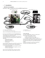
Connection to device - EDP300 Control Unit for remote position sensor
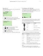
M10834-01
1 2 3
1
4
3
3
2
M 20 mm /
1/2"
NPT
M 20 mm /
1/2"
NPT
1
Terminals for remote position sensor
2
Remote position sensor
3
EMC Cable gland
4
Shielded connection cable
Figure 24: Connection of EDP300 Control Unit with remote position sensor (example)
Change from one to two columns
With the EDP300 designed for remote position sensors, the
positioner is supplied without a position sensor.
The EDP300 Control Unit contains the electronics and
pneumatics along with the following options (where applicable):
• Analog position feedback
• Digital position feedback
• Emergency shutdown module
• Universal
input
Any position sensor (4 to 80 k
έ
) may be connected.
Cable specification
To connect the EDP300 Remote Sensor, a cable with the
following specifications needs to be used:
• 3-wire, cross-section 0.5 to 1.0 mm²
• shielded, with at least 85 % coverage
• Temperature range up to at least 100 °C (212 °F)
The cable glands used must also be approved for a temperature
range up to at least 100 °C (212 °F). The cable glands require a
mounting for the shielding and strain relief for the cable in
addition.
ABB offers suited cables and cable glands with DNV_GL
certification for the EDP300 Remote Version.


