Navigator 600 Phosphate
Multi-stream
4 Installation
20
IM/NAV6P/MS–EN Rev. F
4.6.3 Ethernet Connections
The Ethernet gland is different from the other connections to
accommodate an RJ45 plug:
1. Referring to Fig. 4.9:
a. Turn door retaining screws
A
1
/
4
turn
counter-clockwise and open the electronics section
door.
b. Using a cross-head screwdriver, remove 4 screws
B
and remove transparent cover plate
C
.
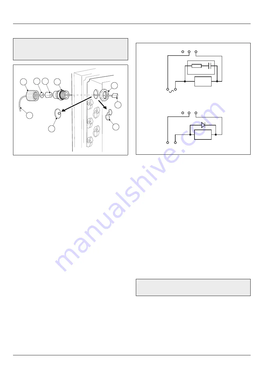
2. Referring to Fig. 4.10:
a. Slide retaining clip
A
off blanking plug
B
and
remove plug.
b. Fit cable gland
C
and secure using nut
D
.
c. Remove gland nut
E
and feed cable
F
through it.
d. Fit split-bush
G
and split-washer
H
to cable
F
.
e. Feed the cable through cable gland
C
and into the
electronics section enclosure.
f.
Plug RJ45 connector
I
into the RJ45 socket on the
application board (see Fig. 4.8, page 18 for location
details) and tighten gland nut
E
.
3. Referring to Fig. 4.9:
a. Replace transparent cover plate
C
and secure with 4
screws
B
.
b. Close the electronics section door and turn door
retaining screws
A
1
/
4
turn clockwise to secure.
4.6.4 Alarm Relay Contact Protection and Interference
Suppression
If the relays are used to switch loads on or off, the relay contacts
can become eroded due to arcing. Arcing also produces RFI
that can cause analyzer malfunctions and incorrect readings. To
minimize the effects of RFI, arc suppression components are
required; these are resistor / capacitor networks for AC
applications or diodes for DC applications. These components
are connected across the load.
Maximum relay ratings are:
250 V, 5 A AC, 1250 VA (non-inductive)
30 V, 5 A DC 150 W
For AC applications, the value of the resistor / capacitor network
depends on the load current and inductance that is switched.
Initially, fit a 100R / 0.022 µF RC suppressor unit. If the analyzer
malfunctions the value of the RC network is too low for
suppression and an alternative value must be used.
For DC applications fit a diode – see Fig. 4.11. For general
applications use an alternative IN5406 type (600 V peak inverse
voltage at 3 A).
Warning.
Remove all power from supply, relay and any
powered control circuits and high common mode voltages
before accessing or making any connections.
Fig. 4.10 Ethernet Connections
A
B
C
D
E
F
G
H
I
Fig. 4.11 Relay Contact Protection
Note.
The minimum voltage must be >12 V and the
minimum current >100 mA for reliable switching.
NC C NO
NC C NO
L N
+ –
C
R
Relay Contacts
External
AC Supply
A – AC Applications
B – DC Applications
External
DC Supply
Relay Contacts
Load
Load
Diode


