


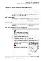


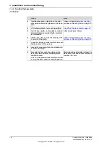


Note
Action
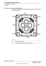
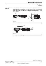
Shown in figure
grooves and leveling bolts on page 70
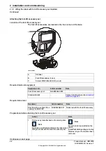
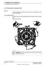
Position base plate in relation to the robot
work location using the
grooves
in the base
plate.
3
See
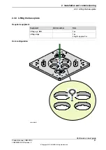
Lifting the base plate on page 67
.
Lift the base plate to its mounting position.
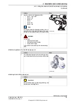
4
Attachment holes: 20 pcs.
Use the base plate as a template and drill at-
tachment holes as required by the selected
bolt dimension.
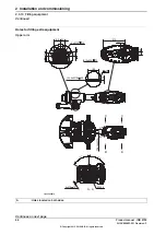
5
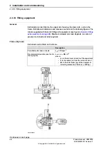
Shown in figure
grooves and leveling bolts on page 70
Fit the base plate and use the levelling bolts
to level the base plate.
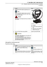
6
If required, fit strips of sheet metal underneath
the base plate to fill any gaps.
7
Secure the base plate to the foundation with
screws and sleeves.
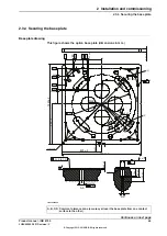
8
Maximum allowed deviation all over the
base plate, from one contact surface to
the other: 0.3 mm.
Recheck the four contact surfaces on the
base plate to make sure the base plate is
levelled and flat.
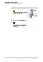
9
If it is not, use pieces of sheet metal or similar
to bring the base plate to a levelled position.
72
Product manual - IRB 8700
3HAC052853-001 Revision: F
© Copyright 2015-2018 ABB. All rights reserved.
2 Installation and commissioning
2.3.4 Securing the base plate
Continued
Summary of Contents for IRB 8700 Series
Page 1: ...ROBOTICS Product manual IRB 8700...
Page 16: ...This page is intentionally left blank...
Page 824: ...This page is intentionally left blank...
Page 838: ...This page is intentionally left blank...
Page 840: ...This page is intentionally left blank...
Page 846: ......
Page 847: ......


