Operation Manual / A150-M56/66/57/67 - A155-M..
10 Dismantling and fitting with removed air inlet and gas outlet / 10.3
Removing the gas outlet flange
© Copyright 2022 ABB. All rights reserved.
HZTL4032_EN
Rev.S
February 2022
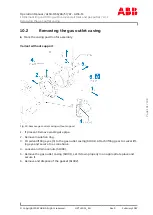
Gas outlet flange with 6 press-off screws
CAUTION
Cracks in the gas outlet casing
Non-observance of the action steps described can lead to inadmissible
cracks on the gas outlet flange.
u
Observe the maximum tightening torques when pressing off.
u
Follow the action steps described.
Dismantle the gas outlet flange only if this is necessary for service work.
u
With blows from a plastic tip hammer, ensure that the gas outlet flange does not cant.
u
If necessary: Treat the centering seat with rust remover through the press-off threads
and the clearance holes.
u
Mark the casing position for assembly.
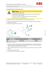
Fig. 54: Removing the gas outlet flange
Product
Press-off screws (strength 8.8) *
Tightening torque
A150
6 x M12 x 30
≤ 65 Nm
A155
6 x M12 x 30
≤ 150 Nm
Table 45: 6 press-off screws
* not included in the Turbo Systems scope of delivery.
1. Evenly press off and remove the gas outlet flange (57002) with screws (01) according to
the table. If the gas outlet flange cannot be pressed off with the maximum tightening
torque, contact a Turbo Systems service station.
2. Attach swivel lifting eye (S) to the gas outlet flange. Secure lifting gear to the swivel lift-
ing eye.
3. Remove the gas outlet flange.
4. If present: Remove the metal C-ring (57003).
Page
106
/
198
Summary of Contents for HT611541
Page 2: ......


