background image

22

(12)

(13)

(15)

(14)

(16)

(17)

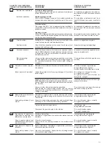
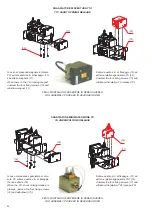
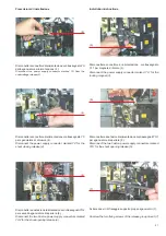
Svitare quattro viti  di fissaggio (13) ed
estrarre relativo sganciatore YU (12).
Unscrew the four fixing screws (13) and
withdraw the relative YU release (12).

In caso di presenza magnete di blocco
YL1 svitare quattro viti  di fissaggio  (10)
ed estrarre magnete (11).
When there is the YL1 locking magnet,
unscrew the four fixing screws (10) and
withdraw magnet (11).

In caso di presenza sganciatore di chiu-
sura YC svitare quattro viti  di fissaggio
(14) ed estrarlo (15).
When the YC shunt closing release is
present, unscrew the four fixing screws
(14) and withdraw it (15).

Svitare quattro viti  di fissaggio  (17) ed
estrarre relativo sganciatore YO1 (16).
Unscrew the four fixing screws (17) and
withdraw the relative YO1 release (16).

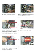
SGANCIATORE DI APERTURA YO1

YO1 SHUNT OPENING RELEASE

SGANCIATORE MINIMA TENSIONE YU

YU UNDERVOLTAGE RELEASE

PER IL MONTAGGIO PROCEDERE IN SENSO INVERSO

FOR ASSEMBLY, PROCEED IN REVERSE ORDER

PER IL MONTAGGIO PROCEDERE IN SENSO INVERSO

FOR ASSEMBLY, PROCEED IN REVERSE ORDER

(11)

(10)

Summary of Contents for HD4-HPA Series

Page 1: ...12 9 Controlli periodici 14 10 Operazioni di manutenzione 15 11 Indicazioni per la manipolazione degli apparecchi con SF6 16 12 Parti di ricambio 17 13 Accessori 18 Index 1 Packing and transport 4 2 Checking on receipt 4 3 Storage 5 4 Handling 6 5 Description 7 6 Instructions for circuit breaker operation 9 7 Installation 11 8 Putting into service 12 9 Periodical checking 14 10 Maintenance operati...

Page 2: ......

Page 3: ...er vento Un comportamento responsabile salvaguarda la vostra e l altrui sicurezza Per qualsiasi esigenza contattare il Servizio Assistenza ABB For your safety Make sure that the installation room spaces divisions and ambient are suitable for the electrical apparatus Check that all the installation putting into service and maintenance operations are carried out by qualified personnel with in depth ...

Page 4: ...i progettazione mediante la scelta mirata dei materiali dei processi e degli imballi Per la fabbricazione degli interruttori sono in atto tecniche di produzione che predispongono i prodotti per un facile smontag gio e una facile separazione dei componenti Ciò al fine di con sentire la massima riciclabilità alla fine del ciclo di vita utile del l apparecchio Introduction This publication contains t...

Page 5: ...lenco ricambi 17 13 Accessori 18 13 1 Caratteristiche degli accessori elettrici 18 13 2 Istruzioni per la sostituzione dei ricambi 19 Index 1 Packing and transport 4 2 Checking on receipt 4 3 Storage 5 4 Handling 6 5 Description 7 5 1 General features 7 5 2 Reference Standards 7 5 3 Withdrawable circuit breaker 7 6 Instructions for circuit breaker operation 9 6 1 Safety indications 9 6 2 Operating...

Page 6: ...e e nella bolla di accompagnamento trasporto Accertare inoltre che nella fornitura siano compresi tutti i materiali descritti nella bolla di spedizione Se al disimballo venisse riscontrato qualche danno o irregola rità nella fornitura avvertire ABB direttamente attraverso il rappresentante o il fornitore il più presto possibile e in ogni caso entro cinque giorni dal ricevimento L apparecchio viene...

Page 7: ...se avoid any accidental impacts or positioning which stresses the structure of the apparatus 3 Magazzinaggio Nel caso sia previsto un periodo di magazzinaggio le nostre officine su richiesta provvedono ad un imballaggio adeguato alle condizioni di immagazzinaggio specificato Al ricevimento l apparecchio deve essere accuratamente disimballato e controllato come descritto al Controllo al ricevi ment...

Page 8: ...ettamente sotto l apparecchio stesso Nel caso in cui fosse necessario utilizzare questa tecnica porre l inter ruttore sopra un robusto piano di supporto vedi fig 3 4 Handling Before carrying out any operation always check that the operating mechanism springs are discharged and that the apparatus is in the open position To lift and handle the circuit breaker use the tool 1 fig 2a shortest hooks Put...

Page 9: ... consentono l aggancio nei corrispon denti incastri del contenitore o parte fissa I blocchi possono essere azionati dalla maniglia posta sul fronte del contenitore solo con interruttore completamente appoggiato al sistema di traslazione La leva di azionamento inserimento sezionamento deve es sere inserita a fondo Un blocco impedisce l avanzamento del carrello nel contenitore o parte fissa per esem...

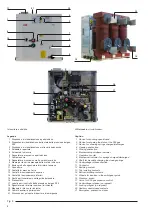
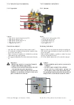
Page 10: ...ontrollo della pressione del gas SF6 18 Sganciatore di minima tensione a richiesta 19 Magnete di blocco a richiesta 20 Contatti ausiliari aperto chiuso 21 Riscontro per pulsante di apertura di emergenza Caption 1 Device for showing open closed 2 Device for showing the state of the SF6 gas 3 Device for showing springs charged discharged 4 Opening pushbutton 5 Closing pushbutton 6 Mechanical open cl...

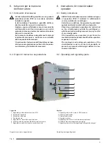
Page 11: ...ore interruttore aperto chiuso 6 Albero per la carica manuale delle mole di chiusura 7 Segnalatore molle di chiusura cariche scariche 6 Instructions for circuit breaker operation 6 1 Safety indications HD4 HPAcircuit breakersensureaminimumdegree of protection IP2X if installed in withdrawable version installed in a switchgear Under these conditions the operator is guaranteed against accidental con...

Page 12: ...dicator 5 and the lamp shows that opening has been accomplished 6 3 Manovre di chiusura e di apertura dell interruttore fig 6 La manovra dell interruttore può essere manuale o elettrica a Manovra manuale di carica molle Per caricare manualmente le molle di chiusura è necessa rio inserire a fondo la leva di carica nella sede 6 e ruotare in senso orario fino alla comparsa del segnalatore 7 di colore...

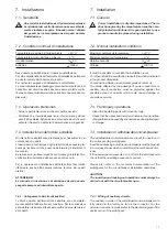
Page 13: ...rante l installazione 7 2 Condizioni normali di installazione Temperatura massima dell aria ambiente 40 C Temperatura minima dell aria ambiente 5 C Umidità relativa 95 Altitudine 1000 m Deve essere possibile areare il locale di installazione Per altre caratteristiche dell ambiente di installazione attenersi a quanto indicato dalle norme di prodotto Per particolari esigenze di installazione contatt...

Page 14: ...iportati nella seguente tabella 8 Putting into service 8 1 General procedures All the operations regarding putting into service must be carried out by ABB personnel or personnel whoaresuitablyqualifiedandhaveanin depthknowl edge of the apparatus and installation If the operations are prevented do not force the mechanical interlocks but check that the operation sequence is correct The operating for...

Page 15: ...ciatore di apertura alla relativa tensione nominale Close the circuit breaker Supply the shunt opening release at the relative rated voltage Aprire l interruttore Alimentare lo sganciatore di chiusura alla relativa tensione nominale Open the circuit breaker Supply the shunt closing release at the relative rated voltage CONTROLLO POSITIVO POSITIVE CHECK La resistenza di isolamento dovrebbe es sere ...

Page 16: ...ed Contatti ausiliari nel comando Auxiliary contacts in the ope rating mechanism Dispositivo di blocco Locking device Dispositivo di blocco con leva sul pannello Locking device with lever on the unit PROCEDURA PROCEDURE Aprire l interruttore Ruotare la chiave ed estrarla dalla sede Tentare la manovra di chiusura dell interruttore Open the circuit breaker Turn the key and remove it Attempt the circ...

Page 17: ...he operating mecha nism and transmission Esame a vista dei contatti sezionamento Visual inspection of the isolating contacts Misura della resistenza di isolamento Measuring the insulation resistance Controllo della funzionalità degli interbloc chi Checking interlock operation 2 3 4 5 6 Dopo 10 000 manovre o dopo 10 anni per installazione in ambienti inquinati ed aggressivi è consigliabile contatta...

Page 18: ...o da personale addestrato e qualificato Le persone da contattare sono indicate sul sito http www abb com ServiceGuide alphabetical aspx A richiesta sono disponibili istruzioni specifiche per svuotare le apparecchiature del gas SF6 richiedere il documento interno 650551 o 1VCP000617 La quantità di gas SF6 contenuta in ogni apparecchio è indicata nella targa caratteristiche 11 Indications for handli...

Page 19: ...iding earthing contact of withdrawable truck Opening closing knob Set of six blade contacts SF6 gas pressure monitoring device Open closed signalling device Charged discharged springs signalling device 12 Parti di ricambio Ogni operazione di montaggio di parti di ricambio accessori deve essere eseguita rispettando le istru zioni allegate ai ricambi stessi da personale ABB o dapersonalecheabbiaunaq...

Page 20: ...tra parentesi è indicata la durata dello spunto Pc Potenza assorbita in servizio continuativo T Costante di tempo 13 1 Caratteristiche degli accessori elettrici Un Rated voltage Cosϕ ϕ ϕ ϕ ϕ Power factor Icu Breaking capacity Ps Inrush power consumption the inrush time is indicated in brackets Pc Continuous service power consumption T Time constant 13 1 Characteristics of electrical accessories Sh...

Page 21: ...ssere effettuate con interruttore all interno dello scom parto in situazione di sicurezza Make sure that the circuit breaker springs are discharged With circuit breaker protections removed pay attention to any moving parts Before starting installation operations isolate the power supply to the auxiliary services For further details please refer to the instruction manual Caution Put the installatio...

Page 22: ...nciatore di chiusura 4 Disconnect the power supply connector marked YC for the shunt closing release 4 Disconnettere due faston di alimentazione contrassegnati YO1 per sganciatore di apertura 5 Disconnect the two Faston power supply connectors marked YO1 for the shunt opening release 5 Disconnettere due faston di alimentazione contrassegnati YO2 per sganciatore di apertura 6 Disconnect the two Fas...

Page 23: ...ed in reverse order Svitare numero quattro viti di fissaggio ed estrarre magnete 9 Unscrew the four fixing screws and withdraw magnet 9 Svitare numero quattro viti di fissaggio ed estrarre sganciatore 8 Unscrew the four fixing screws and withdraw release 8 SGANCIATORI DI CHIUSURA YC YC SHUNT CLOSING RELEASES MAGNETE DI BLOCCO YL1 YL1 LOCKING MAGNET PER IL MONTAGGIO PROCEDERE IN SENSO INVERSO FOR A...

Page 24: ...e di chiu sura YC svitare quattro viti di fissaggio 14 ed estrarlo 15 When the YC shunt closing release is present unscrew the four fixing screws 14 and withdraw it 15 Svitare quattro viti di fissaggio 17 ed estrarre relativo sganciatore YO1 16 Unscrew the four fixing screws 17 and withdraw the relative YO1 release 16 SGANCIATORE DI APERTURA YO1 YO1 SHUNT OPENING RELEASE SGANCIATORE MINIMA TENSION...

Page 25: ...ignalling of the operating mechanism springs 4 Check operation of the motor limit microswitch 5 Check operation of the transient contact with momentary closing during circuit breaker opening If operation is correct proceed to fix the cover as indicated in figure A For any problems please contact us Verifiche funzionali prima della messa in servizio dell interruttore Operare come segue 1 Alimentare...

Page 26: ...uttore all interno dello scom parto in situazione di sicurezza Make sure that the circuit breaker springs are discharged With circuit breaker protections removed pay attention to any moving parts Before starting installation operations isolate the power supply to the auxiliary services For further details please refer to the instruction manual Caution Put the installation out of service and under ...

Page 27: ...ve the two motor limit microswitch fixing screws 2 Sganciare molla di ritorno 3 alzare coppia nottolini di carica e spingere leva in avanti 4 Prescrizioni di installazione Installation instructions Release the return spring raise the pair of charging pawls and push the lever forwards 4 ...

Page 28: ...one del motore 7 Premere con una punta la chiavetta di collegamento situata sull albero motore e ruotare la camma motore per accedere alle viti di fissaggio 5 With a bit press the connection key located on the motor shaft and turn the motor flange to access the fixing screws 5 Unscrew the motor flange fixing screws 6 Disconnect the motor power supply 7 ...

Page 29: ... con interruttore all interno dello scom parto in situazione di sicurezza Make sure that the circuit breaker springs are discharged With circuit breaker protections removed pay attention to any moving parts Before starting installation operations isolate the power supply to the auxiliary services For further details please refer to the instruction manual Caution Put the installation out of service...

Page 30: ...s 2 Togliere protezione per l alimentazione del microinterruttore 3 Remove the microswitch power supply protection 3 Prescrizioni di installazione Installation instructions PER IL MONTAGGIO CONNETTERE I FILI COME NELLA POSIZIONE ORIGINARIA 4 TO ASSEMBLE CONNECT THE WIRES IN THEIR ORIGINAL POSITION 4 Disconnect the microswitch connection 4 ...

Page 31: ...necessary information for correct intervention Responsible behaviour safeguards your own and others safety For any request please contact us Prescrizioni generali General instructions Per la vostra sicurezza Mettere in sicurezza la parte di impianto su cui si deve operare Le operazioni di seguito descritte devono essere effettuate da personale con una adeguata conoscenza dell apparec chiatura e de...

Page 32: ...nual Prescrizioni preliminari Preliminary instructions Caution Put the installation out of service and under safe conditions Cut off the power supply to the auxiliaries Check that the circuit breaker springs are discharged by means of the appropriate signal The operations described below can be carried out safely with the circuit breaker inside the cubicle Attenzione Mettere fuori servizio e in si...

Page 33: ...se 2 Disconnettere connettore di alimentazione contrassegnato YL1 per magnete di blocco 3 Disconnect the power supply connector marked YL1 for the locking magnet 3 Disconnettere connettore di alimentazione contrassegnato YC per sganciatore di chiusura 4 Disconnect the power supply connector marked YC for the shunt closing release 4 Disconnettere due faston di alimentazione contrassegnati YO1 per s...

Page 34: ...For assembly proceed in reverse order Sganciare tirante di collegamento ausiliari con albero principa le e tenerlo sollevato 9 Svitare due viti di fissaggio gruppo contatti ausiliari 10 Release the auxiliary connection tie rod with the main shaft and kept it raised 9 Unscrew the two fixing screws of the auxiliary Eliminare fascette di tenuta separando il cablaggio dei contatti ausiliari dal resto ...

Page 35: ......

Page 36: ...s Oberhausener Strasse 33 Petzower Strasse 8 D 40472 Ratingen D 14542 Glindow Phone 49 0 2102 12 1230 Fax 49 0 2102 12 1916 E mail calor info de abb com www abb com Dati e immagini non sono impegnativi In funzione dello sviluppo tecnico e dei prodotti ci riserviamo il diritto di modificare il contenuto di questo documento senza alcuna notifica The data and illustrations are not binding We reserve ...

Reviews: