Electrical
connection
D184B141U02
FSM4000
EN - 19
4.2
Connecting the flowmeter sensor
4.2.1 Connecting the signal and magnet coil cables
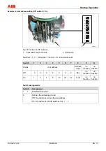
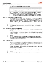
The flowmeter sensor is connected to the transmitter via the signal / magnet coil cables (part
nos. D173D025U01 / D173D147U01). The coils of the flowmeter sensor are supplied with a
excitation voltage by the transmitter over terminals M1/M3. Connect the cables to the flowmeter
sensor according to the following drawing, using a screwdriver with proper size and width.
G00
553
SE
SE
3A
3A
1S
2S
1
2
3
16
16
M1
M3
1
2
3
6
5
7
4
6
9
8
G00
554
SE
SE
3A
3A
U-
U+
1
2
3
16
16
M1
M3
1
2
3
6
5
7
4
6
9
8
Fig. 22
1
red
2
blue
3
yellow
4
white
5
black
6
SE clamp
7
Signal cable
8
Grounding screw
9
Magnet coil cable
1
red
2
blue
3
yellow
4
white
5
black
6
SE clamp
7
Signal cable
8
Grounding screw
9
Magnet coil cable
Terminal designation Connection
1 + 2
Wires for the measuring signal
1S, 2S
Shielding for signal wires
U+, U-
Power supply for preamplifier via signal cable shielding
16
Cable for reference signal
3A
Shielding for reference signal cable
3 Measuring
ground
(yellow)
M1 + M3
Connections for magnetic field excitation (black)
SE Outer
cable
shield
Summary of Contents for FSM4000 Series
Page 2: ......
Page 46: ...Appendix 44 EN FSM4000 D184B141U02...
Page 47: ...Appendix D184B141U02 FSM4000 EN 45...
Page 48: ...Appendix 46 EN FSM4000 D184B141U02...
Page 49: ......


