background image


(13) 


11 


E) Switching from the «connected» position to the 
«test isolated" position.


E) Перевод из положения CONNECT (вкачен) в 
TEST (контрольное положение).


Repeat the operations indicated in point «D» in 
reverse order. 

Выполните действия, указанные в п. D, 
в обратном порядке. 

F) Switching from the «test isolated" position to the 
«disconnected» position. 

F) Перевод из положения TEST (контрольное 
положение) в DISCONNECT (отсоединен). 

Repeat the operations indicated in point «C» in 
reverse order. 

Выполните действия, указанные в п. С, 
в обратном порядке. 

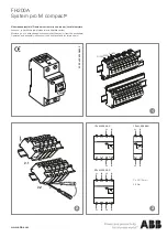
Remove the withdrawal lever if it is still inserted 
(fig. 14). 

Withdraw the moving part by hand through to the 
stop point in the «racked out» position. 

Если рычаг для выдвижения оставался 
вставлен, выньте его (рис. 14). 

Руками вытащите выдвижную часть до упора 
в выкаченном положении. 


Fig. 14  Рис. 14 ——————————————————————————————————————— 


PUSH 

BEFORE  

OPERATING


НАЖАТЬ


ПЕРЕД


ОПЕРИРОВАНИЕМ


CONNECT 

ПОДСОЕДИНИТЬ


TEST 

ТЕСТ


DISCONNECT 

ОТСОЕДИНИТЬ


Summary of Contents for Emax

Page 1: ...uit breaker of the same size as indicated in table A to be racked into the fixed part of Emax Emax E1 E6 800 6300 Emax Emax 2 A Table A A Emax 2 800 1000 1250 1600 2000 2500 3200 4000 5000 6000 Emax E...

Page 2: ...er question please contact ABB ABB ATTENTION Instructions regarding the retrofitting kit assembling are not intended as replacement of the installation and maintenance manuals of the Emax 2 new circui...

Page 3: ...02 1 INSERTION AND EXTRACTION OPERATIONS Before inserting the Emax 2 circuit breaker follow the installation instructions 1SDH0010000R0002 Complete a cycle of no load operations with the Emax 2 new ci...

Page 4: ...controlled by the operator before any operation in order to prevent useless stress c the accidental pression of the push button 1 fig 1 bring to lock the circuit breaker operativity DON T OPERATE THE...

Page 5: ...E4 2 E6 2 E4 E4 2 Vertical axis E4 2 3P 3 E4 2 Vertical axis E4 2 4P 4 E4 2 Position the adhesive template on the door and make sure that the dotted line perfectly matches the aperture on the door its...

Page 6: ...red holes E1 E2 E3 E6 E2 2 E4 2 E6 2 E4 E4 2 3 4 Fig 5 5 If the dotted line on the adhesive template fails to perfectly match the existing opening in the door cut a new door as indicated by the positi...

Page 7: ...7 5 Assemble the dust guard flange of the compartement door E1 E2 E3 E6 E2 2 E4 2 E6 2 Fig 7 7 4 4 2 1 Nm 1 1 Nm 1 1 Nm 1 2 Nm 2...

Page 8: ...8 6 Fit the pins A and if present replace the components D E F as shown in the figure 8 A D E F 8 Fig 8 8 40 Nm 40 40 Nm 40 New Emax Emax Old Emax Emax...

Page 9: ...The circuit breakers should be lifted by lift truck Use of ropes is however permitted 9 The Direct Replacement retrofitting kit fig 9 has supports 1 allowing it to be lifted 9 1 Fig 9 9 The manual plu...

Page 10: ...B DISCONNECT Push the moving part through to the stop point in the disconnected position 1 In this position the compartment door can be i closed and the circuit breaker operated in the manual mode fig...

Page 11: ...h button 2 Insert the handle 1 into its seat fig 12 Now turn the handle to the automatic locking position at which the lever push button 2 will return to its inoperative position The circuit breaker i...

Page 12: ...eration described in point C until reaching the automatic operation locking position The switch is in the connected position fig 13 In this position all the electrical operations can be performed and...

Page 13: ...F Switching from the test isolated position to the disconnected position F TEST DISCONNECT Repeat the operations indicated in point C in reverse order Remove the withdrawal lever if it is still insert...

Page 14: ...ig 16 16 13 Remove all the tools used for the work and eliminate any waste and scraps of the materials used 14 Putting into service and maintenance of the new circuit breaker Consult the installation...

Page 15: ...chboard Dimensions mm Emax E1 E2 Emax 2 E2 2 E F 3 F1 4 G E F 3 F1 4 G 500 400 490 380 500 400 490 355 Emax E3 Emax 2 E4 2 E F 3 F1 4 G E F 3 F1 4 G 500 500 630 380 500 500 600 355 Emax E4 Emax 2 E4 2...

Page 16: ...ing bracket 1 and the protection 2 Be careful not to damage the wiring of the auxiliary circuits Proceed with the disassembly of the arc chute according to the user and maintenance manual for Emax 2 1...

Reviews: