IB 6.2.11.1-1C
Installation/Maintenance Instructions
Low Voltage Power Circuit Breaker
K-Line Plus
®
Type KP-8 thru KP-20
ABB
Page 1: ...IB 6 2 11 1 1C Installation Maintenance Instructions Low Voltage Power Circuit Breaker K Line Plus Type KP 8 thru KP 20 ABB ...
Page 2: ...Representative CONTENTS PAGE INTRODUCTION 3 QUICK REFERENCE FOR UNCRATING INSPECTION AND INSTALLATION 3 CIRCUIT BREAKER ESCUTCHEON FEATURES 4 CIRCUIT BREAKER INTERNAL COMPONENTS 6 K LINE PLUS CIRCUIT BREAKER CRADLE FEATURES 7 SOLID STATE TRIP SYSTEM 8 OPERATING SEQUENCE FOR ELECTRICALLY OPERATED EO CIRCUIT BREAKERS 9 CLOSING SPRING OPERATION MO 10 INSTALLATION INITIAL TESTING AND REMOVAL 10 MAINTE...
Page 3: ...akers immediately upon receipt Examine shipping cartons to determine if any damage or loss was sustained during transit When such damage is evident file a damage claim with the carrier and notify your ABB sales office ABB is not responsible for damage of goods after delivery to the carrier but will assist when notified of claims The period of time after shipment that claims can be filed is short s...
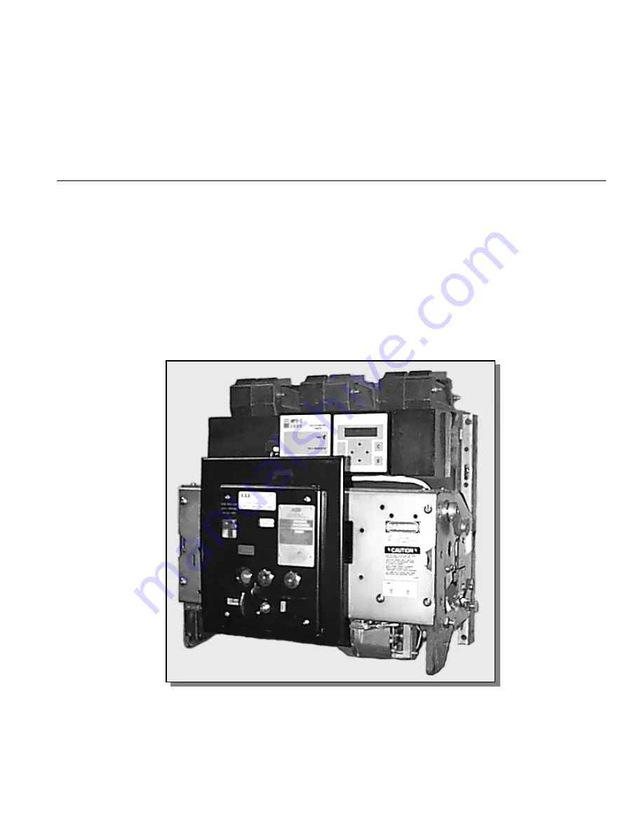
Page 4: ... circuit breaker can be racked to the connected position using a procedure similar to 12 above CIRCUIT BREAKER ESCUTCHEON FEATURES The K Line Plus low voltage power circuit has a number of standard features and can be equipped with numerous other optional features Refer to Figure 1 as the features are discussed below Circuit Breaker Nameplates There are two nameplates on the circuit breaker The br...
Page 5: ...dle 9 OPEN or CLOSED Indicator 10 Manual Trip Button 11 Escutcheon Assembly 12 Manual Close Lever 13 Padlock Hasp 14 Motor Disconnect Switch 15 Automatic Trip Indicator 16 Removable Maintenance Handle 17 Position Indicator 18 Spring Charging Motor 19 Positioning Pins 20 Side Latches 21 Racking Cam Assembly Figure 1 Typical Electrically Operated K Line Plus Circuit Breaker ...
Page 6: ... The racking shutter of all K Line Plus circuit breakers allows access to the racking shaft when lifted The circuit breaker must be tripped before the shutter can be lifted This prevents racking the circuit breaker with the main contacts closed The padlock hasp holds the racking shutter closed when the hasp is activated Instructions appear on the side of the front escutcheon of the circuit breaker...
Page 7: ...positions This switch is located in the lower left portion of the circuit breaker Optionally EO breakers and MO breakers with shunt trip can be fitted with a 16 pole switch which offers an additional four each a and b contacts for customer use Undervoltage Trip Device Optional The electrically reset undervoltage trip device UVD is a single phase device which automatically trips the circuit breaker...
Page 8: ...Optional Interconnected cradle mounted linkage permits only one of two horizontally or vertically adjacent circuit breakers to be closed at any time when in the CONNECTED position KIRK Key Interlock Optional Positions for mounting a KIRK Key interlock are available with accessibility through the closed compartment door The Kirk Key is released only when the linkage on the cradle locks the circuit ...
Page 9: ...result from failure to properly adjust the circuit breaker trip device To adjust the settings of the MPSC 2000 trip device see the instructions in IB 6 1 2 8 1A A trip operation indicator or target is provided on the face of the MPSC 2000 unit When the MPSC 2000 determines that a trip is necessary it will both signal the magnetic latch and display the trip target with an orange day glo color Since...
Page 10: ...rgized All tests of the circuit breaker should be done with the circuit breaker in the TEST position Installation To insert the circuit breaker into its mating cubicle proceed as described below 1 The circuit breaker contacts must be OPEN and the racking crank turned in the counterclockwise direction fully against its stop On electrically operated circuit breakers the motor disconnect switch shoul...
Page 11: ...C 1 51 2 a AS Trip Control Device 5 P18 A5 P4 P20 P8 2 P6 A2 P2 P19 P22 P1 P10 Solid State 3A 1 3 A3 P17 4 Trip A4 2 P5 4A 1 7 P9 P3 80 19 17 15 A14 A18 A16 23 21 A22 A20 14 18 16 20 22 A15 A21 A19 A17 A23 5 6 AS a 10 AS 9 a 12 AS 11 b 14 AS 13 a 16 AS 15 b 53 65 CSCS CSCS 64 63 56 57 NO C C NO B21 32 31 B22 B13 B9 B11 B7 34 32 36 B15 B17 B19 38 40 42 44 19 17 18 a AS 20 21 23 b AS 22 AS a 24 35 3...
Page 12: ...ot Used pin out assignments 6 The assignments for pins B3 B6 will differ depending on whether the DESP option has been supplied See the MPSC 2000 schematic supplied with the breaker Notes 1 These assignments are provided for reference only and may be changed due to special requirements Some pins or plugs may not be present on all breaker configurations See the breaker schematic wiring diagram s fo...
Page 13: ...ance handle hooked section in the long slot on the pawl carrier Refer to Figure 4 The small tab on the maintenance handle will fit the small hole of the pawl carrier Using a pumping motion rotate the pawl carrier until the ratchet wheel no longer rotates At this point the spring charged indicator will indicate SPRINGS CHARGED The circuit breaker can be closed manually with the manual close lever N...
Page 14: ...s necessary to charge the closing springs and or operate the circuit breaker during maintenance keep hands and tools away from operating parts Circuit breakers should be withdrawn to the TEST position for checking the breaker operation For further inspection adjustments cleaning or parts replacement the circuit breaker should be withdrawn and moved to a suitable work area Periodic Maintenance Insp...
Page 15: ...xcess soot from the arc chute and blow any excess away with clean dry compressed air Arc Chute Replacement 1 Properly position the arc chute in the upper molding 2 Position retainer and insert and tighten screw 3 Replace the MPSC 2000 trip device observing all recommendations and warnings above Contact Inspection 1 Discoloration signs of burning and pitting on the arcing contacts is normal unless ...
Page 16: ...ason for making any adjustment the locking hardware will become ineffective when adjustments are made at each maintenance period regardless of whether they are needed or not Operating experience indicates that the contact gap adjustment is the only one normally required during the periodic maintenance interval When contacts are replaced or abraded during cleaning contact gap adjustment is mandator...
Page 17: ... service operation with the charging cranks reset and the closing springs discharged CONTACT PRESSURE Refer to Figure 8 The main contact adjustment is to be made with the breaker in the latched closed position The self locking adjusting stud 1 is to be turned to provide contact pressure such that a 0 750 inch shim will just fit the space A at the rear of the moving main contacts 2 On 800A models w...
Page 18: ...ripping the circuit breaker 4 Back off the adjusting screw 3 approximately two full turns Tripper Bar Latch Engagement Refer to Figure 9 The tripper bar latch engagement adjusting screw 4 is located adjacent to the latch engagement adjusting screw 3 To adjust the tripper bar latch engagement proceed as follows 1 Back off the adjusting screw 4 to assure excessive tripper bar travel 2 Close the circ...
Page 19: ...ed voltage to terminals 3 and 5 of the circuit breaker secondary disconnects Magnetic Latch Device The magnetic latch device in K Line Plus breakers does not require adjustment PROCEDURE FOR FIELD TESTING THE MPSC 2000 SOLID STATE TRIP SYSTEM There are two ways to evaluate the MPSC 2000 solid state trip system primary current injection through the breaker main contacts and secondary current inject...
Page 20: ...7 The term Range Selection is used herein for consistency with previous MPS type devices and refers to the value of the Rating setting of the device Like the previous MPS type devices the MPSC 2000 is capable of operating at two basic ratings one equal to the maximum frame continuous current rating and one equal to one half the frame rating For example on an 800A breaker the MPSC 2000 rating can b...
Page 21: ...ompletely assembled circuit breaker and not on individual parts Temperature At Which Tests Are To Be Made Dielectric tests shall be made at any temperature between 10 C and 55 C Magnitudes And Points of Application Of Test Voltage The dielectric test shall be applied as follows 1 With circuit breaker in the open position apply 1 320 volts a Between live parts including both line and load terminals...
Page 22: ...B p n 712994 A00 Anderol synthetic lubricant is also available as a spray Anderol 732 Anderol 732 is useful as a solvent for removing old lubricant dirt and debris in the mechanism However it cannot be used as a substitute for Anderol 757 4 Apply DAG 154 Acheson Colloid Inc to the following parts in accordance with ABB Specification 51626 a The surface of the secondary close latch b The main shaft...
Page 23: ...IB 6 2 11 1 1C Page 23 ABB NOTES ...
Page 24: ...IB 6 2 11 1 1C Page 24 ABB NOTES ...
Page 25: ...IB 6 2 11 1 1C Page 25 ABB NOTES ...
Page 26: ...IB 6 2 11 1 1C Page 26 ABB ABB Inc P O Box 100524 Florence South Carolina 29501 Phone 843 413 4700 Fax 843 413 4850 ABB ...