


2
2
ELECTRICAL INSTALLATION
This section describes the connection of serial data transmission cables between
the master (host computer) and slave instruments on a MODBUS serial link. All
connections other than those used for serial communication are shown in Section
5 of the relevant
User Guide.
2.1
Host Computer Serial Communications
An RS422/485 communications driver must be fitted to the host computer. It is
strongly recommended that the interface has galvanic isolation to protect the
computer from lightning damage and increase signal immunity to noise pick-up.
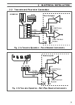
2.2
Two-wire and Four-wire Connection – Figs. 2.1 and 2.2
MODBUS serial communications must be configured as either two-wire or four-wire
serial links – see Figs. 2.1 and 2.2. Two-/four-wire operation must also be selected
in the Configuration Mode – see Section 3.1.
1
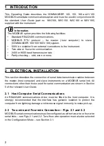
INTRODUCTION
This Operating Guide describes the COMMANDER 100, 150, 160 and V100
MODBUS serial data communications option and must be used in conjunction with
the standard
User Guide (part no. IM/C100, IM/C150, IM/C160 or IM/V100)
supplied with the instrument.
Information.
The MODBUS option provides the following facilities:
•
Standard RS422/485 communications.
•
MODBUS RTU protocol – for master (host computer) to slave
(COMMANDER 100/150/160/V100) system.
•
500V d.c isolation from external connections to the instrument.
•
Two-wire or four-wire communication.
•
2400 or 9600 baud transmission rate.
•
Parity-checking – odd, even or none.


