


9
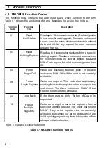
This section shows typical examples of MODBUS function codes 01, 03, 05, 06, 08
and 16. Not all addressable parameters used in the examples which follow are valid
for all instrument types – see Sections 7.1 to 7.4.
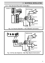
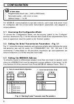
5.1
Read Coil Status – Function Code 01
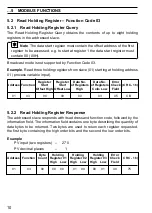
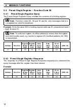
5.1.1
Read Coil Status Query
This function obtains the ON/OFF status of logic coils used to control discrete
outputs from the addressed slave. Broadcast mode is not supported with this
function code. In addition to the slave address and function fields, the information
field must contain the initial coil offset address (starting address) and the number of
each location to be interrogated.
Note. The coil offset address is one less than the coil number, e.g. to
start at coil 06 the start address must be set to 05 (05H).
Example. Read 16 coils from slave (01) starting at coil 6 (alarm state 1).
Address Function Coil Start
Coil Start
No. of
No. of
Error Check ( C R C - 1 6 )
Offset High Offset Low Coils High Coils Low
Field
01
01
00
05
00
10
2D
C7
5.1.2
Read Coil Status Response
The data is packed one bit for each coil (1 = ON, 0 = OFF). The response includes
the slave address, function code, quantity of data characters, the data characters
and error checking. The low order bit of the first character contains the first
addressed coil and the remainder follow. For coil quantities that are not multiples of
eight, the last characters are packed with zeros at the high order end.
Example
Alarms 1, 2 and 3 inactive
Digital input inactive
Digital output inactive
Relays 1 and 2 active
ON/OFF status 1 and 2 active
Data Coil
Data Coil
Error Check
(CRC-16)
Address
Function
Byte Count
Status
Status
Field
6 to 13
14 to 21
01
01
02
00
3E
38
2C
5
MODBUS FUNCTIONS


