


7
3
MECHANICAL INSTALLATION…
3
/
8
in NPT
Female
Thread
112 mm
65 mm
approx.
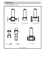
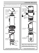
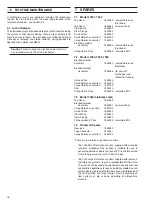
A – Type 7651
B– Type 7660
174 mm (6
7
/
8
in)
235 mm (9
1
/
4
in approx)
44 mm (1
3
/
4
in)
1in BSPT
Female
Thread
Optional 1in. Nom.
Bore Pipe Flanges
Drilled to BS10
Table E
1
/
2
in BSPT or
NPT Female
Thread
Bosses M10 x 1.5
Internal Thread
Top Cover
274
mm (10
3
/
4
in)
Allow about 150 mm free space above the
top cover for access and removal of the cover.
44 mm (1
3
/
4
in)
Bosses M10 x 1.5
Internal Thread
250
mm (10
in approx)
110
100
90
80
70
60
50
40
30
20
10
0
20
40
60
80
100
Temperature T/
C
Pressure/
(psi
)
Pressure/
(bar)
7
6
5
4
3
2
1
0
20
40
60
80
100
70
60
50
40
30
20
10
0
5
4
3
2
1
Temperature T/
C
Pressure/
(psi
)
Pressure/
(bar)
160
140
120
100
80
60
40
20
0
10
9
8
7
6
5
4
3
2
1
0
20
40
60
80
100
Temperature T/
C
Pressure/
(psi
)
Pressure/
(bar)
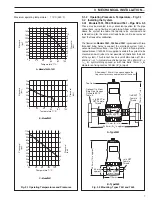
B –Model 7652
A –Models 7660 & 7651
C –Model 7661
Maximum operating temperature:
110°C (230°F)
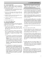
3.1.2
Operating Pressure & Temperature – Fig. 3.1
3.2
Installing the System
3.2.1
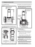
Models 7651, 7652, 7660 and 7661 – Figs. 3.2 & 3.5
These may be mounted in any convenient position for the pipe
connections, using flexible or rigid piping. Allow sufficient space
above the system to enable the top cap to be unscrewed and
removed and for the entire electrode holder unit to be removed
from the flowcell for calibration.
The flowcell on
Models 7651, 7660 and 7661
is provided with two
threaded fixing holes to support the electrode system from a
convenient vertical surface – see Figs. 3.2 and 3.5. Also, a plastic-
coated bracket (7600 960) is supplied to enable the system to be
mounted on a wall (when it is not possible to fit bolts from the back
of the system). This bracket has an overall dimension of 164 x
60mm (6
1
/
2
x 2
3
/
8
in) diameter on fixing centres 140 x 40mm (5
1
/
2
x
1
9
/
16
in), symmetrically spaced, or with two bolts 12mm (
1
/
2
in)
diameter on fixing centres 140mm (5
1
/
2
in) apart.
Fig. 3.1 Operating Temperatures and Pressures
Fig. 3.2 Mounting, Types 7651 and 7660


