


9
3
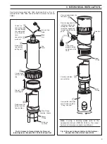
MECHANICAL INSTALLATION…
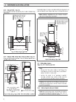
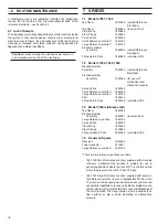
Thread the
connecting cable
tag ends through
the cable gland
at the top of the
cover.
Stem Flange
Locating Groove
Unscrew and
remove clamp
ring.
Slide off
stem flange.
5
4
2
C o n n e c t i n g
Cable
Top
Cover
Remove sensor
holder from the
flow chamber.
6
Lower
'O' Ring
Gland
Nut
3
Remove the
top cover by
pulling it off.
Loosen the
gland nut.
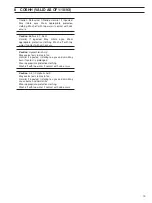
1
Reference
Junction
Upper
'O' Ring
Lower
'O' Ring
Side Port
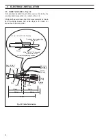
Unscrew the immersion
skirt. Ensure the lower
'O' ring is not lost.
Carefully withdraw
sensor holder.
Unscrew and remove the
top cover.
1
2
3
Drop the plug end of the
cable assembly down
through the tube and
thread the tagged end
through one of the side
ports.
4
Fit the gland
provided, but do
not tighten at this
stage.
5
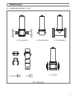
See Fig. 3.6 for models 7651, 7652, 7660 and 7661, or Fig. 3.7
models 7654, 7655, 7656, 7664 and 7665, to access the sensor
holder.
Fig. 3.6 Access to Sensor Holder for Flow and
In-line Systems – Models 7651, 7652, 7660 and 7661
Note.
If using a cleaning option refer to the
appropriate manual (IM/7600–CLN) as the sensor
holder and reference electrode are different.
Fig. 3.7 Access to Sensor Holder for Dip Systems –
Models 7654, 7655, 7656, 7664 & 7665


