ABB AnalyzeIT 7600 Series Instruction Manual Download Page 18

16

6

ROUTINE MAINTENANCE

6.1

‘O’ Ring Seals

Whenever the electrode system is opened at any point, all
'O' rings (especially the lower sensor holder 'O' ring), seals,
washers, etc. should be checked for damage, wear and flexibility,
and unserviceable rings must be replaced. Serviceability very
much depends on the particular application, but regular checking
soon determines an average ring life.

A spare set of 'O' rings is supplied with each system, and
replacement 'O' rings, etc. are available in a Service Pack. Spares
are listed in Section 7.

6.2

Cleaning

When the performance of the electrodes begins to deteriorate,
cleaning may help to restore their original condition. If the cleaning
actions described in this section do not eliminate the deterioration,
either the glass (or redox) electrode, or the sealed reference
electrode or both should be replaced. These steps are described
in Section 6.4.

If the system is fitted with a mechanical or ultrasonic electrode
cleaning device, refer to the instruction manual IM/7600-CLN for
details of cleaning procedures.

During cleaning, avoid rough handling of the pH glass electrode
membrane. Wiping with a soft cloth or tissue soaked in an
appropriate solvent to remove the deposit, or washing with a
strong jet of water are preferred methods – this can be carried out
by removing the electrode holder unit from the process fitting; it
should be unnecessary to remove the electrodes from the sensor
holder. However, where the following cleaning operation requires
an extended period it is advisable to replace the electrode during
cleaning with a new one so that there is a minimum interruption to
the on-line process measurement.

Caution

. Hydrochloric acid is corrosive. Wear

appropriate protective clothing.

1) For general sludge and loosely adhering matter wipe the glass

membrane with cotton wool soaked in 1.0M hydrochloric acid
(or a buffer solution) and then wash in water. Now calibrate the
pH meter.

2) For greasy organic deposits, wipe the glass membrane with

cotton wool soaked in a detergent and rinse thoroughly. If a
sluggish response to pH changes still occurs soak the
electrode for a few hours in 0.1M hydrochloric acid (or a buffer
solution) and then wash in water.

3) For heavy non-greasy deposits, e.g. rust, dip the electrode

briefly in concentrated hydrochloric acid to remove the deposit
and wash thoroughly. Soak the electrode for a few hours in
0.1M hydrochloric acid (or a buffer solution) and then wash in
water. Very heavy deposits formed during effluent
neutralisation are often best removed by using a 1 : 1 mixture
of concentrated hydrochloric acid and water. Pepsin digested
in hydrochloric acid may also be used for protein removal.

4) The Reference Junction of the reference electrode may be

cleaned by washing in water and wiping with a clean cloth.

5) Redox electrodes may be cleaned by any of the previously

described methods; they may also be cathodically cleaned as
follows:

Caution

. Sulphuric acid is corrosive. Wear

appropriate protective clothing.

Degrease the electrode, e.g. with a detergent. Connect the
redox electrode cable to the negative pole of a 6V battery or
power supply. Connect a piece of platinum wire to the positive
pole of the battery or power supply, and dip both electrodes
into a beaker containing 2 to 5% sulphuric acid solution.
Continue electrolysis for approximately 10 minutes. If after
this period the bubbles rising from the redox electrode are not
small and evenly distributed on the immersed parts of the
electrode, repeat the electrolysis.

6.3

Checking the Electrolyte Level

Periodically check the level of electrolyte (about every three
months).

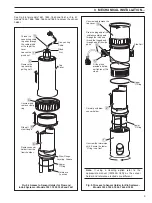
For sealed units remove the electrode holder from the system.
Refer to Fig. 3.8a. Invert the holder and remove the reference
junction. View the electrolyte level through the plug hole and top
up if necessary.

6.4

Replacing Electrodes

6.4.1

Measuring Electrodes

If the pH or redox electrode is no longer serviceable (see Section
6.5) fit a new electrode. The procedure is as follows:
1) For a flow system isolate the system to enable safe access to

the sensors. In the case of a dip system, remove it from its
installed position in the fixing clamp(s).

2) Remove the electrode holder unit from the process fitting (the

protective skirt on a dip system), and take out the sensor
holder from the bottom end of the electrode holder unit.

3) Replace the electrode with a new one following the steps

outlined in Section 3.3.3.

4) Calibrate the pH meter or electrode system as outlined in the

pH meter instruction manual.

5) Install the electrode holder unit.

Summary of Contents for AnalyzeIT 7600 Series

Page 1: ...Analyze IT pH ORP Electrode System 7600 Series Instruction Manual IM 7650_7 ...

Page 2: ...nts are not to be reproduced in full or part without prior approval of the Technical Publications Department Health and Safety To ensure that our products are safe and without risk to health the following points must be noted 1 The relevant sections of these instructions must be read carefully before proceeding 2 Warning labels on containers and packages must be observed 3 Installation operation m...

Page 3: ... and 10 the Temperature Compensator 1750 000 10 3 3 4 Completion Tasks Fig 3 11 11 3 4 Fitting the Reservoir 12 4 ELECTRICAL INSTALLATION 13 4 1 Connection to 4500 and 4600 Series Transmitters 13 4 2 Connection to Hazardous Area Systems 13 4 3 Cable Termination 14 5 CALIBRATING THE SYSTEM 15 6 ROUTINE MAINTENANCE 16 6 1 O Ring Seals 16 6 2 Cleaning 16 6 3 Checking the Electrolyte Level 16 6 4 Repl...

Page 4: ...nch in line system with 2 inch BS10 Table E flange fittings Model 7654 polypropylene 1 metre nominal dip system Model 7664 PVDF 1 metre nominal dip system Model 7655 polypropylene 2 metre nominal dip system Model 7665 PVDF 2 metre nominal dip system Model 7656 polypropylene 3 metre nominal dip system Dip systems are for use in tanks channels etc All the above models are compatible with the AX 4500...

Page 5: ...3 2 PREPARATION A 7651 Polypropylene B 7660 Stainless Steel C 7652 Polypropylene E 7661 PVDF 7654 7664 D Polypropylene 7655 PVDF 7665 7656 2 1 Checking the Code Number Fig 2 1 Fig 2 1 System Types ...

Page 6: ...itted Low Resistance Electrode 1722 000 low resistance membrane electrode for low temperature low conductivity applications For use in the water industry where the sample temperature drops below 10 C 50 F Operates from 0 to 10 pH 0 to 70 C 32 to 158 F Note For conductivities less than 30 µS cm 1 a stainless steel system is recommended High Temperature Electrode 1724 000 for use on high temperature...

Page 7: ...r u t a r e p m e t 0 0 1 T P 0 0 0 0 5 7 1 s r e t a w e l b a t o p r o f d e d n e m m o c e R 2 e d o r t c e l e s s a l g d e p a h s e n o c 0 0 0 1 2 7 1 e d o r t c e l e e c n e r e f e r d r a d n a t s 0 0 0 0 3 7 1 r o t a s n e p m o c e r u t a r e p m e t 0 0 1 T P 0 0 0 0 5 7 1 s n o i t a c i l p p a l a i r t s u d n i r o f r e n a e l c c i n o s a r t l u h t i w d e s u e b ...

Page 8: ...rying out periodically check and top up the flowcell reservoir with clean water or buffer solution 3 1 Siting 3 1 1 Operating Limits Model 7651 Flow Type see Fig 3 1A for details pH range 0 to 14 Operating temperature range 0 to 100 C 32 to 212 F Maximum operating temperature 100 C at 2 1bar 212 F at 30psi Maximum operating pressure at 25 C 77 F 10 6bar 150psi Model 7652 In line Type see Fig 3 1B ...

Page 9: ...ture 110 C 230 F 3 1 2 Operating Pressure Temperature Fig 3 1 3 2 Installing the System 3 2 1 Models 7651 7652 7660 and 7661 Figs 3 2 3 5 These may be mounted in any convenient position for the pipe connections using flexible or rigid piping Allow sufficient space above the system to enable the top cap to be unscrewed and removed and for the entire electrode holder unit to be removed from the flow...

Page 10: ...13 16 in 222 mm 8 3 4 in Allow about 150 mm 6 in free space above the top cover for access and removal of the cover 3 2 2 Model 7652 Fig 3 3 This is installed and held in position by the 2 in BS10 Table E fixing flange only 3 2 3 Models 7654 7655 7656 7664 and 7665 Fig 3 4 These are dip systems installed in any convenient position over the open tank or channel 3 3 Fitting Electrodes Figs 3 6 3 7 3...

Page 11: ...Carefully withdraw sensor holder Unscrew and remove the top cover 1 2 3 Drop the plug end of the cable assembly down through the tube and thread the tagged end through one of the side ports 4 Fit the gland provided but do not tighten at this stage 5 See Fig 3 6 for models 7651 7652 7660 and 7661 or Fig 3 7 models 7654 7655 7656 7664 and 7665 to access the sensor holder Fig 3 6 Access to Sensor Hol...

Page 12: ...h f When a path has been cleared position the electrode and screw down firmly to ensure a good seal g Shake the sensor holder to ensure that the KCl slurry reaches the bottom of the chamber h Invert the sensor holder and remove the reference junction Fig 3 8 Check the level of the slurry top up if necessary Refit reference junction There are two reference junctions available 1360 180 Small Referen...

Page 13: ...ove Connector Lower Section Connectors Upper Section 3 3 4 Completion Tasks Fig 3 11 Reassemble in the reverse order to that shown in the steps in Fig 3 6 or Fig 3 7 Before fitting the Top Cover however connect the colour coded electrode cables to the appropriate electrodes see Fig 3 11 Finally tighten the gland nut to secure the connecting cable Fig 3 10 Location of Blanking Plug and Reservoir Tu...

Page 14: ...tion to avoid creating a vacuum Filler Cap Sensor Holder 1 Push tubing onto the fitting on the sensor holder Tighten the connector firmly 2 3 4 6 a Partially Assembled Reservoir b Fully Assembled Reservoir c Filling the Reservoir Pull off the filler cap 6 7 Replace the filler cap ensuring the O ring is in place 8 9 Note Ensure that the reservoir tube is not kinked and does not contain air bubbles ...

Page 15: ... 3 1 3 1 3 h t r a E n o i t u l o S h t r a e 5 2 A N 3 2 A N 4 1 Connection to AX 4500 and 4600 Series Transmitters Fig 4 1 and Table 4 1 System cable connections to the pH meter are shown in Fig 4 1 For AX and 4600 series transmitters refer to the pH meter instruction manual For 4500 Series transmitters refer to the list of equivalent connections shown in Table 4 1 4 2 Connection to Hazardous A...

Page 16: ...en Co axial Cable Preparation Wire 16 0 2 PVC covered soldered to screen Trim back black conductive layer to here Fig 4 3 Cable Termination 4 3 Cable Termination Fig 4 3 If the provided standard length cable requires shortening the recommended preparation is as shown in Fig 4 3 Strip back the overall cable sheath to measurements as shown and fit suitable sleeves and solder tags to the leads for co...

Page 17: ...etails of the procedure are given in the instruction manual for the pH meter to which reference should now be made The method for immersing the electrodes in the buffer solutions is simply by removing the electrode holder unit from its process fitting and dipping the electrodes in a small beaker of the appropriate buffer solution For dip systems wash the electrodes with demineralised water and imm...

Page 18: ...n and then wash in water 3 For heavy non greasy deposits e g rust dip the electrode briefly in concentrated hydrochloric acid to remove the deposit and wash thoroughly Soak the electrode for a few hours in 0 1M hydrochloric acid or a buffer solution and then wash in water Very heavy deposits formed during effluent neutralisation are often best removed by using a 1 1 mixture of concentrated hydroch...

Page 19: ...changed and should be given attention see 3 following Note SLOPE value and CHECK readings can be affected by low insulation on the electrode terminations Always check for any evidence of moisture in the electrode terminations 3 The sealed double junction reference arrangement used on this pH system requires regular maintenance The frequency of this maintenance depends greatly on the application Fa...

Page 20: ... Assembly 7650056 for use with mechanical and ultrasonic cleaners Service Pack 7650040 Small Reference Junction 1360180 Large Reference Junction 1360190 Skirt 7603410 Filling Soln 3 Pack 7650039 saturated KCl 7 3 Model 7660 stainless steel Top Cover 7650064 Electrode Holder Assembly 7650051 reservoir Fed Large Reference junction 1360190 Service Pack 7660040 Clamp Ring 7600640 Stem Flange 7600590 F...

Page 21: ...with tap water if contact with skin occurs Caution Hydrochloric Acid May evolve toxic fumes in fire Harmful if ingested Irritating to eyes and skin May burn if contact is prolonged Wear appropriate protective clothing Wash off with tap water if contact with skin occurs Caution 2 5 Sulphuric Acid May evolve toxic fumes in fire Harmful if ingested Irritating to eyes and skin May cause burns and derm...

Page 22: ...20 NOTES ...

Page 23: ...cs Instrumentation pH conductivity and dissolved oxygen transmitters and sensors ammonia nitrate phosphate silica sodium chloride fluoride dissolved oxygen and hydrazine analyzers Zirconia oxygen analyzers katharometers hydrogen purity and purge gas monitors thermal conductivity Customer Support We provide a comprehensive after sales service via a Worldwide Service Organization Contact one of the ...

Page 24: ...ithout notice Printed in UK 09 04 ABB 2004 ABB Limited Oldends Lane Stonehouse Gloucestershire GL10 3TA UK Tel 44 0 1453 826661 Fax 44 0 1453 829671 ABB Inc Analytical Instruments 9716 S Virginia St Ste E Reno Nevada 89521 USA Tel 1 775 850 4800 Fax 1 775 850 4808 ABB has Sales Customer Support expertise in over 100 countries worldwide www abb com ...

Reviews: