


20
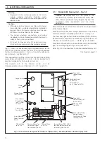
Electrical
Interconnections
Flow Gauge
Gas Sample
Outlet
Local Zero
Adjustment
Drying Chamber
Katharometer
Unit Case
Metering
Valve
Gas
Sample
Inlet
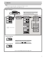
6.1
Katharometer Analyzer Panel –
Filling the Drying Chamber – Fig. 6.1
1) Remove the drying chamber on the katharometer analyzer
panel by unscrewing the large knurled nut at the base of the
chamber. Pull the chamber down and out of the sealing
groove to remove it from the panel.
Note
. The desiccant used in the drying chamber is
either granular anhydrous calcium sulphate or calcium
chloride and absorbs moisture from the atmosphere.
The drying chamber has a capacity of 140ml approx.
and requires approx. 100g of desiccant to fill it. Filling
and resealing must be carried as quickly as possible.
2) Open a container of fresh desiccant and fill the drying
chamber.
3) Replace the drying chamber in its sealing groove and
reposition the chamber to enable it to be secured and sealed
by hand tightening the knurled nut.
4) Carry out an approved leak testing procedure before passing
sample gas through the system.
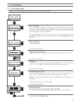
6.2
Setting Sample Flow
When all tubing interconnections have been made and external
parts of the sample system checked for leaks, carry out the
following procedure:
1) Supply calibration quality CO
2
or Argon through the gas
analyzer system at the normal working pressure of the
application plant and within the following limits:
Model 6540-203
125mm H
2
O min. to 0.35bar (gauge) max.
Model 6548-000
125mm H
2
O min. to 10bar (gauge) max.
Note
. In some instances testing for leaks with CO
2
or
argon may not be considered an adequate check of
gas tight integrity in respect of the more penetrating
hydrogen gas. Consideration should be given to the
use of a gas, such as helium, which has penetrating
properties nearer to that of hydrogen.
2) Slowly open the metering valve to give a nominal flowrate of
gas of 100 to 150ml min
–1
. Do not exceed the maximum
flowrate 250ml/min.
3) Set the flowrate and shut off the calibration gas external to
the analyzer system.
4) Repeat this procedure for each katharometer analyzer panel,
as required.
Fig. 6.1 Location of Components on Katharometer Analyzer Panel
6
SETTING UP


