


15
Exter
nal
power supply
TB2
1
2
3
4
5
6
7
8
9
10
Kathar
ometer
Unit
Gas Panel 2
*
TB1
1
2
3
4
5
6
7
8
9
10
Kathar
ometer
Unit
Gas Panel 1
TB1
TB2
Power Supply Unit 2
Model
4234
LN
E
TB1
TB2
Power Supply Unit 1
LN
E
Exter
nal
power supply
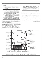
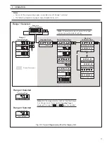
Note
. Inter
connections
marked with MUST conform to the
intrinsically safe wiring r
equir
ements
given in the text.
All other wiring to suit power and signal
requir
ements
Outputs as r
equir
ed (upper and lower displays identical)
Zener diode safety
barrier devices
Exter
nal dual
power supply
Connections for
Lower Display
Connections for
Upper Display
L N E
L
N
E
123456789
1
0
11
12
13
14
15
16
TB4
NO
NC
NO
NC
COM
COM
Remote
Range
(if fitted)
H
2
in Air
Alarm 1
H
2
in Air
V
alue
Retransmission
+
–
123456789
1
0
1
1
1
2
1
3
1
4
1
5
1
6
Exter
nal bonding
and earth
TS1
H
2
in Air
Alarm 2
TB3
17
18
19
20
B1
4 3
B2
4 3
TB5
TB6
TB1
TB2
Note.
Kathar
ometer Gas Unit Panel 1 is connected inter
nally within 6553 Gas Monitor to Upper Display
.
Kathar
ometer Gas Unit Panel 2 is connected inter
nally within 6553 Gas Monitor to Lower Display
.
B1
4 5
B2
4 5
MTL 7755ac
MTL 7055ac
*
*
*
*
*
*
Note
. Not applicable to AK103.
*
Model
4234
Monitor
Common
Range 3
Range 2
Range 1
+
–
+
–
+
–
+
–
+
–
+
–
Fig. 5.3 Inter
connection Wiring Diagram – Models AK102 & AK103 Intrinsically Safe Analyzer System using Dual 3-range Displays,
as Separate Units
5
ELECTRICAL INSTALLATION…


